Bolt torque detection device

A torque detection and bolt technology, applied in the field of bolt torque detection devices, can solve the problems of high labor intensity, low input-output ratio, large errors, etc., and achieve the effect of overcoming inaccurate loading, low cost and low price

Active Publication Date: 2013-11-27
TAICANG ZHONGBO RAILWAY FASTENER
View PDF17 Cites 20 Cited by
  • Summary
  • Abstract
  • Description
  • Claims
  • Application Information

AI Technical Summary

Problems solved by technology

The former method has the characteristics of simplicity, quickness, and low cost, but it has the disadvantages of large error, difficult to control torque acceleration, and high labor intensity.
Although the latter method is accurate in measurement, complete in data, intuitive and credible, the friction coefficient testing machine is extremely expensive and has a single function. It can only measure the friction coefficient and torque when the bolt is rotating, and the input-output ratio is not large.

Method used


Image

  • Bolt torque detection device
  • Bolt torque detection device
  • Bolt torque detection device

Examples


Embodiment 1

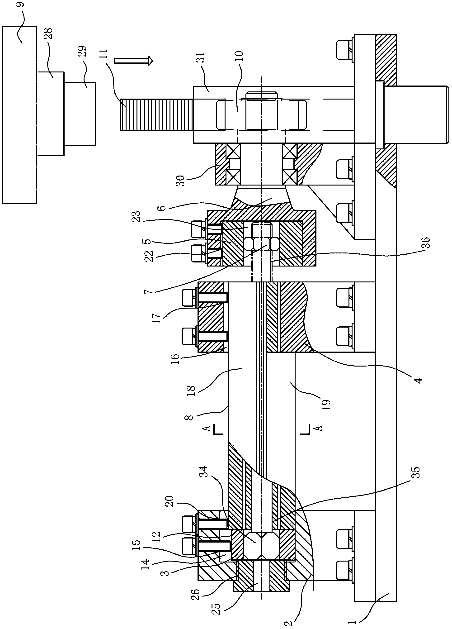
[0035] Embodiment one: see Figure 1-7 As shown, a bolt torque detection device includes a machine base 1 on which a head support seat 2, a gear seat 30 and a rack seat 31 are fixed, and the detection device also includes a head chuck 3 , nut chuck 5, rotating sleeve 6, nut 7, tensile testing machine 9, gear 10, rack 11 and back cap 25;

[0036] The rack 11 slides vertically up and down on the rack seat 31, the gear 10 is supported by the gear seat 30 and rotates around the horizontal line, the gear 10 is coaxially connected with the rotating sleeve 6, the gear 10 and the rack 11 mesh, and the tensile testing machine 9. Drive and connect the rack 11 to drive the rack 11 to slide, and drive the gear 10 and the rotating sleeve 6 to rotate;

[0037] The head support seat 2 is provided with a connected head support seat hole 14 and a head chuck pressing screw hole 15, the head chuck 3 is inserted into the head support seat hole 14, and the head clamp After the screw is assembled...

Embodiment 2

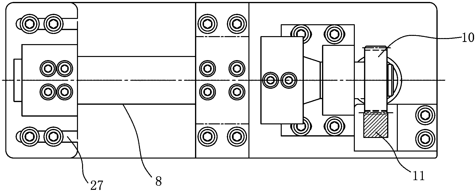
[0049] Embodiment two: see Figure 8As shown, a bolt torque detection device has the same basic structure as the first embodiment, and also includes a rod support seat 4 and a rod pressing block 8; Hole 32, the rotation sleeve through hole 32 is axially horizontal, the bolt thread section 36 in the corresponding nut chuck hole 23 of the hole, the bolt head 34 of the corresponding bolt of the described back cap hole 26 holes, and the back cap hole 26 size is larger than the bolt The size of the head 34; the horizontal distance between the rod support seat 4 and the nut chuck 5 is greater than the thickness of the nut 7, unscrew the screw in the head chuck pressing screw hole 15, and loosen the nut chuck pressing screw Screw in the hole 22, unscrew the screw in the screw hole 17 at the right end of the pressure block on the rod, unscrew the screw in the screw hole 20 at the left end of the pressure block on the rod, and use the push rod 33 to extend into the through hole 32 of t...


PUM


Abstract

A bolt torque detection device is characterized in that a rack slides up and down in the vertical direction on a rack base, wherein the rack is supported by the rack base to rotate around a horizontal line, the rack is coaxially connected with a rotating sleeve, and a tension tester is in transmission connected with the rack and drives the rack to slide; a head chuck is placed in a head supporting base hole to limit rotation of the head chuck around the horizontal line and relative to the head supporting base; rotation of a bolt head around the horizontal line and relative to the head chuck is limited; rotation of a nut chuck around the horizontal line and relative to the rotating sleeve and translation of the nut chuck along the horizontal line are limited; rotation of a nut around the horizontal line and relative to the nut chuck is limited; the nut and the bolt head are the same in height; the head supporting base is provided with a back cap hole, the end of a back cap stretches into the head supporting base hole to abut against the head chuck and the bolt head of a bolt in the head chuck, and leftward movement of the bolt head along the horizontal line and rotation of the bolt head around the horizontal line are limited. The bolt torque detection device is practical, precise, intuitive, rapid, convenient to use and low in cost and price.

Description

technical field [0001] The invention relates to a torque detection device, in particular to a bolt torque detection device. Background technique [0002] bolt, see Figure 6 , generally has a hexagonal bolt head 34, and a cylindrical or square rod-shaped screw 35 connected to the bolt head 34, and the part of the screw rod 35 away from the bolt head 34 also has a threaded segment 36. Bolts are widely used in construction, mechanical engineering, railways, ships, wind power generation, air transportation and other industries. Torque is an important inspection item for bolts. At present, the torque detection of bolt parts is mainly using a torque tester (also known as a torque wrench, which can apply torque and display the torque value for monitoring), and manually fix the bolt head of the tested bolt in a bench vise On the end of the screw, use a torque wrench to apply force, so that the screw rotates at a certain angle around the screw axis relative to the fixed bolt head,...

Claims


Application Information

Patent Timeline
Patent Type & Authority Applications(China)
IPC IPC(8): G01L5/24
Inventor 何萍林波
Owner TAICANG ZHONGBO RAILWAY FASTENER
Why Eureka
Try Eureka