Quasi-optical phase correction surface designing method

A phase correction and phase technology, applied in computing, special data processing applications, instruments, etc., can solve the problems that the phase correction surface cannot be reached, the purity of the high Gaussian beam mode, etc.

Inactive Publication Date: 2013-11-27
UNIV OF ELECTRONICS SCI & TECH OF CHINA
View PDF2 Cites 9 Cited by
  • Summary
  • Abstract
  • Description
  • Claims
  • Application Information

AI Technical Summary

Problems solved by technology

[0007] In order to overcome the technical defect that the correction of the phase correction surface in the prior art cannot achieve

Method used


Image

  • Quasi-optical phase correction surface designing method
  • Quasi-optical phase correction surface designing method
  • Quasi-optical phase correction surface designing method

Examples


Embodiment Construction

[0027] The specific embodiment of the present invention will be further described in detail below in conjunction with the accompanying drawings.

[0028] A method for designing a quasi-optical phase correction surface, including X-direction perturbation of the quasi-optical phase correction surface design method, the perturbation

[0029] -----①

[0030] in is the phase of the Y-direction component of the reverse Gaussian beam electric field at the phase correction plane, is the phase of the Y-direction component of the forward beam electric field at the phase correction plane; is the wave number, α is the forward beam incident angle;

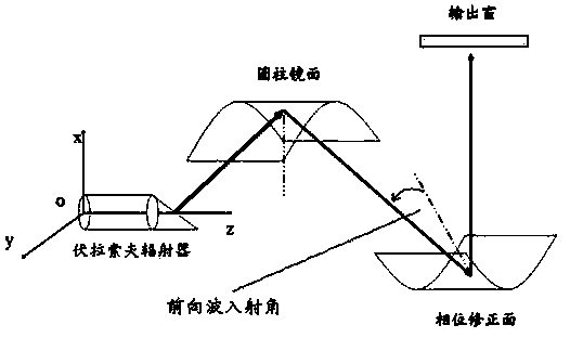
[0031] The above subscripts 1 and 2 represent the reverse Gaussian beam and the forward beam respectively, such as figure 1 As shown, the beam from the cylindrical mirror to the phase correction surface is the forward beam, and the Gaussian beam from the output window to the phase correction surface is the reverse Gaussian beam. Mo...


PUM


Abstract

A quasi-optical phase correction surface designing method comprises a designing method of X-direction perturbation delta X of a quasi-optical phase correction surface. The quasi-optical phase correction surface designing method is characterized in that the perturbation delta X is equal to a quotient obtained by dividing the difference of phi Ey1 and phi Ey2 by 2k0cosine alpha, wherein phi Ey1 is the phase of a reverse Gaussian wave beam electric field Y-direction component in the position of the phase correction surface, phi Ey2 is the phase of a forward wave beam electric field Y-direction component in the position of the phase correction surface, k0 represents the wave number, alpha represents a forward wave beam incident angle, the phi Ey2 represents the forward wave beam electric field Y-direction component phase calculated with a vector diffraction theory, phi Ey1 is a Gaussian beam function, that is, phi Ey1 is equal to phi Ey1 (U), and U represents Gaussian beam. The adopted quasi-optical phase correction surface designing method which is used for designing a phase reflection surface with a vector diffraction theory is different from a scalar diffraction theory method, and the phase reflection surface is more accurate while compared with a phase reflection surface designed with a scalar diffraction theory.

Description

technical field [0001] The invention belongs to the field of physical electronics and relates to microwave devices, in particular to a method for designing a quasi-optical phase correction surface. Background technique [0002] The high-frequency output structure of the built-in quasi-optical mode converter of the high-power gyrotron is mainly composed of a Vlasov launcher and a multi-stage mirror. Multi-level reflectors can be divided into general regular mirrors and phase correction surfaces. The general regular mirrors focus the microwaves radiated from the radiator and do not have the effect of phase correction. [0003] like figure 1 The typical implementation of the high-frequency output structure of the built-in quasi-optical mode converter of the above-mentioned high-power gyrotron is shown. The microwave is reflected from the cutout of the Vlasov radiator through the cylindrical mirror to the phase correction surface, and then from the output Window output, the mi...

Claims


Application Information

Patent Timeline
IPC IPC(8): G06F17/50
Inventor 赵青刘建卫
Owner UNIV OF ELECTRONICS SCI & TECH OF CHINA
Why Eureka
Try Eureka