
A quick disconnecting device for enameled wire of electric motor
A technology for enameled wires and motors, which is applied in the field of quick disassembly devices and disassembly devices for enameled wires of electric motors. It can solve the problems of burnt stator coils, easy to pull the iron core, and difficulty in disassembly, and achieve the effect of reducing work intensity and uniform disassembly force
- Summary
- Abstract
- Description
- Claims
- Application Information
AI Technical Summary
Problems solved by technology
Method used
Image

Examples
Embodiment 1
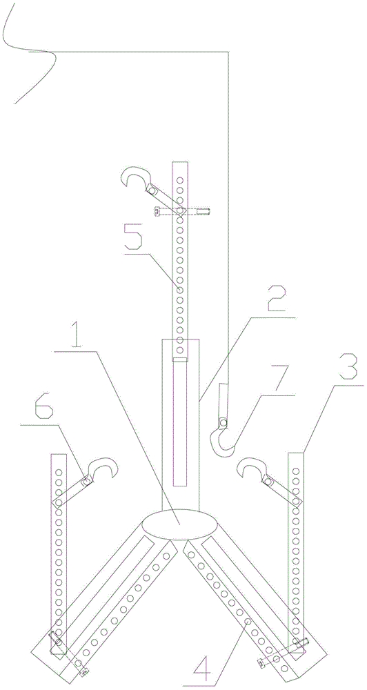
[0011] This embodiment provides a quick disconnecting device for enameled wires of electric motors, such as figure 1 As shown, it includes a central base 1 and an extension arm 2 connected to the central base 1 at one end, a support column 3 is slidably connected to the extension arm 2, and the groove walls on both sides of the chute of the extension arm 2 are provided along the length direction The chute positioning through hole 4, the end of the supporting column 3 connected to the extension arm 2 is provided with a through hole matching the chute positioning through hole 4, and the supporting column 3 is provided with a hook height adjustment hole 5 along the length direction, and the hook The claw 6 is fixed in one of the claw height adjustment holes 5, and a single-beam driving hook 7 for pulling out the enameled wire is fixedly arranged above the center base 1 .
[0012] figure 1 Only three extension arms are shown in the figure, which are evenly distributed with the c...
PUM
 Abstract
Description
Claims
Application Information