Ultrasonic transducer, ultrasonic probe, and ultrasonic examination device

An inspection device and ultrasonic technology, applied in ultrasonic/sonic/infrasonic diagnosis, material analysis using sonic/ultrasonic/infrasonic waves, measurement devices, etc., can solve problems such as the decrease of ultrasonic sensitivity, and achieve the effect of improving level and sensitivity

Active Publication Date: 2013-12-04
SEIKO EPSON CORP
View PDF1 Cites 2 Cited by
  • Summary
  • Abstract
  • Description
  • Claims
  • Application Information

AI Technical Summary

Problems solved by technology

That is, the reception and transmission characteristics of ultrasonic

Method used


Image

  • Ultrasonic transducer, ultrasonic probe, and ultrasonic examination device
  • Ultrasonic transducer, ultrasonic probe, and ultrasonic examination device
  • Ultrasonic transducer, ultrasonic probe, and ultrasonic examination device

Examples


Embodiment Construction

[0043] Hereinafter, a detailed description will be given based on preferred embodiments of the ultrasonic transducer, ultrasonic probe, and ultrasonic inspection apparatus of the present invention shown in the drawings.

[0044]

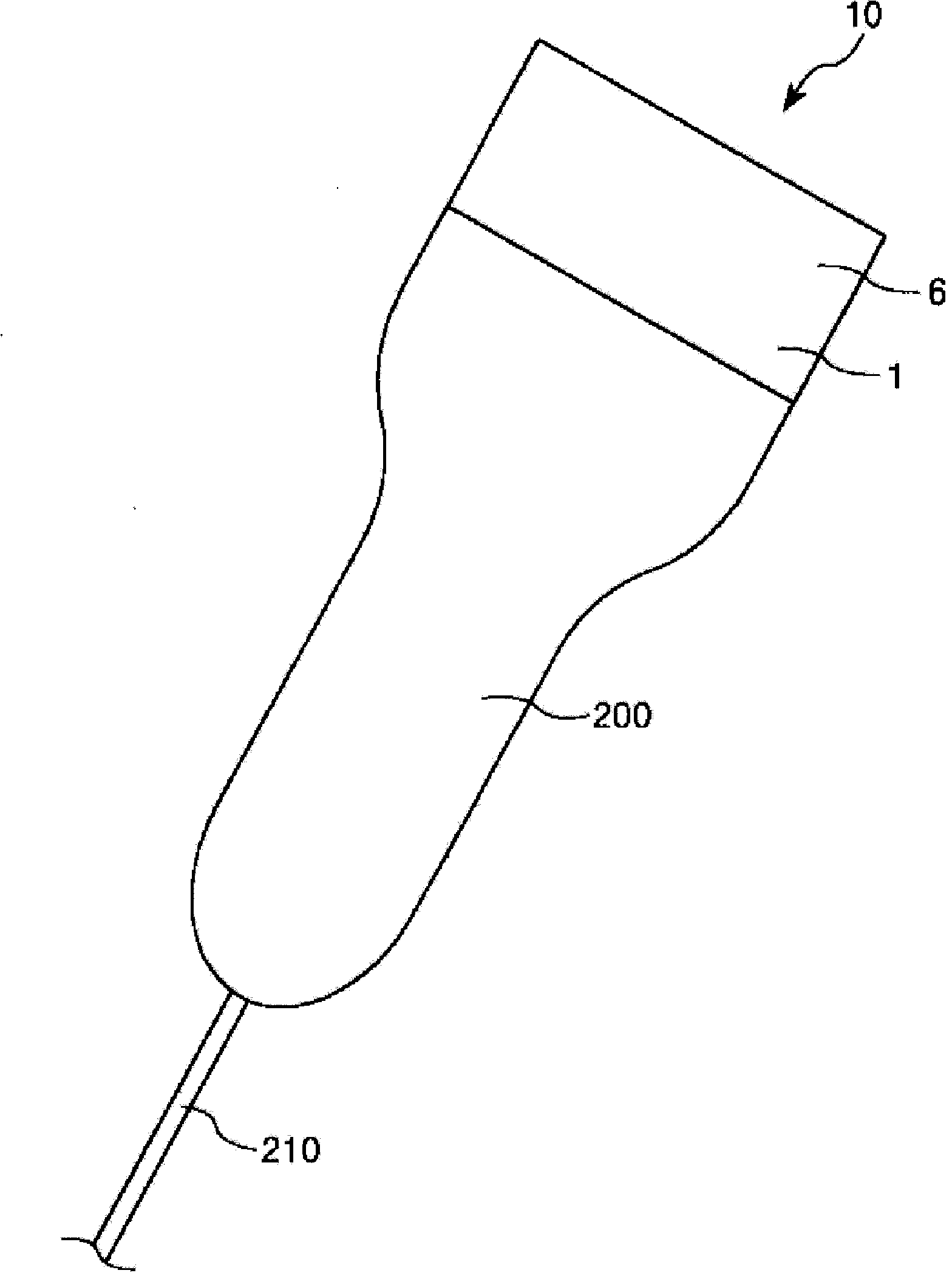
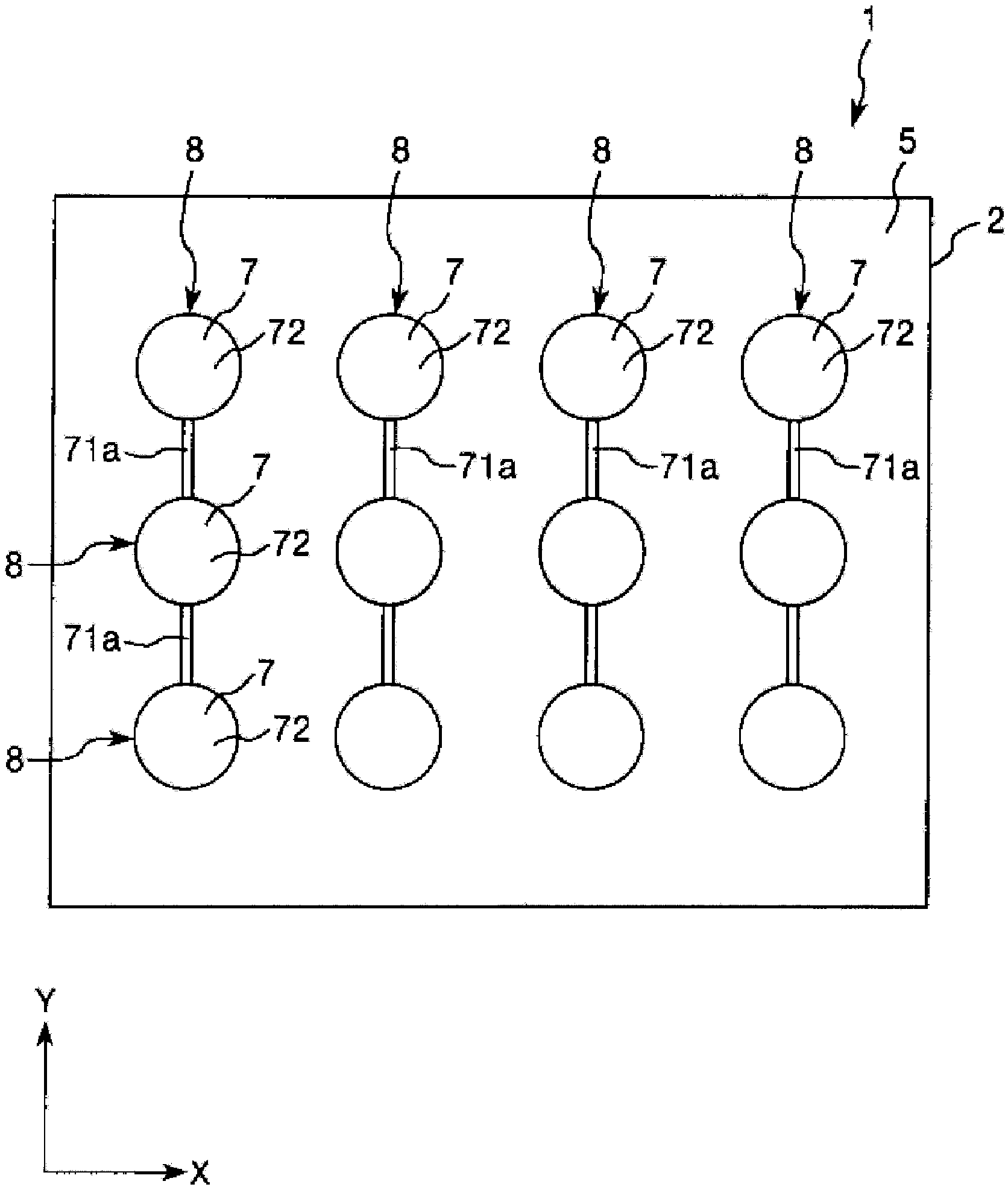
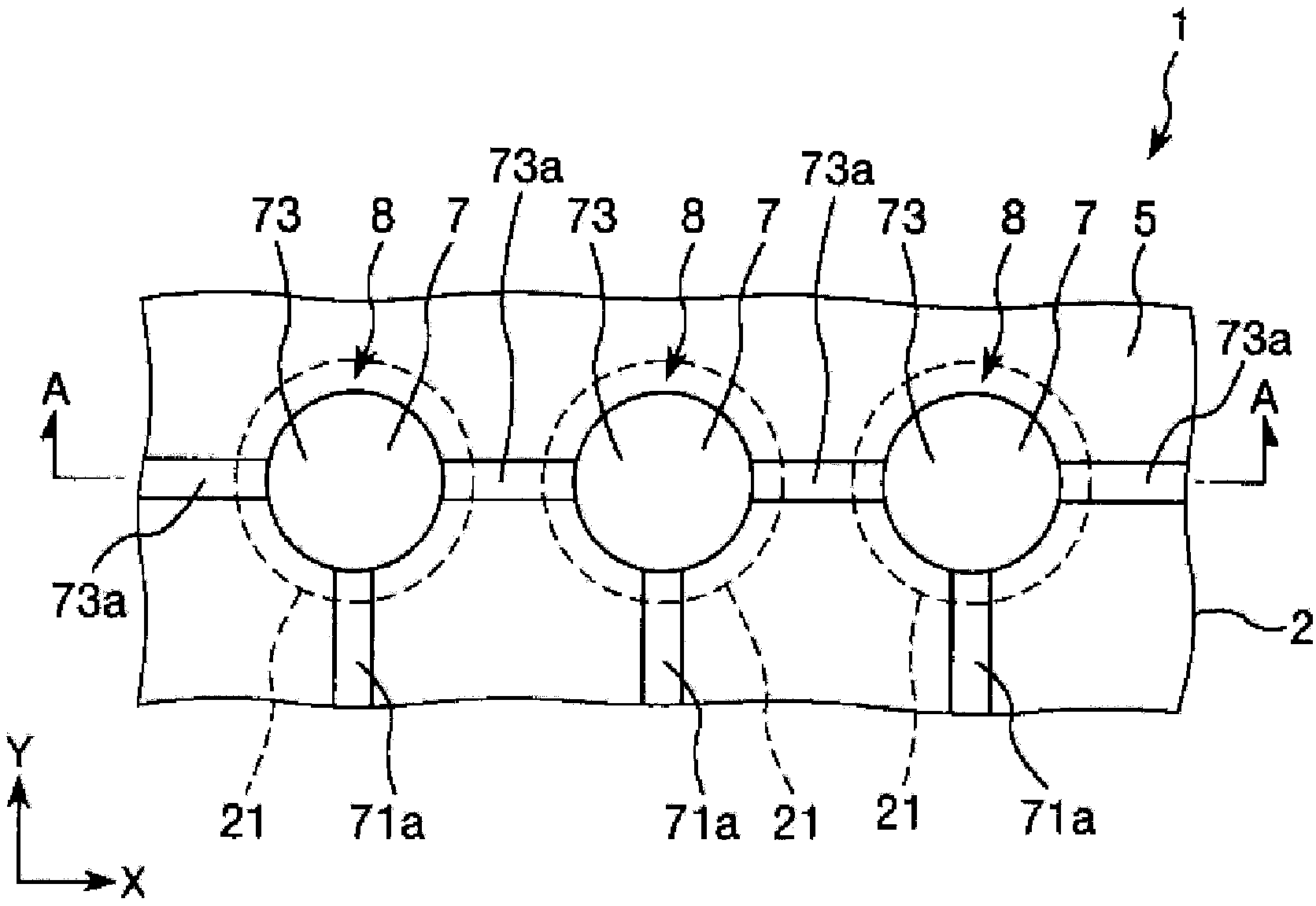
[0045]figure 1 is a perspective view showing an embodiment of the ultrasonic probe of the present invention, figure 2 is showing figure 1 The top view of the ultrasonic transducer of the ultrasonic detector shown, image 3 is zoomed in figure 2 A partial top view of the ultrasonic transducer shown, Figure 4 is along image 3 A cross-sectional view of line A-A in, Figure 5 is zoomed in Figure 4 A partial cross-sectional view of the ultrasonic transducer shown, Figure 6 to Figure 8 is for illustration figure 1 A cross-sectional view of a manufacturing method of an ultrasonic transducer of an ultrasonic probe is shown.

[0046] Moreover, in the following, the Figure 3 to Figure 7 The upper side among them will be described as "upper", ...


PUM


Abstract

An ultrasonic transducer (1) includes a substrate (2), a supporting film (5), and a piezoelectric element (7). The substrate (2) includes an opening (21). The supporting film (5) is configured on the substrate (2) to cover the opening (21). The piezoelectric element (7) is configured at a part of the supporting film (5). The part overlaps with the opening (21) in a planar view in a thickness direction of the substrate (2). A thickness of the part of at a center of gravity in the planar view is smaller than a thickness of an outer edge portion of the part. The outer edge portion is closer to the substrate (2) than the center to the substrate (2).

Description

technical field [0001] The invention relates to an ultrasonic transducer, an ultrasonic detector and an ultrasonic inspection device. Background technique [0002] An ultrasonic transducer configured by arranging a plurality of ultrasonic elements in a matrix is ​​known. [0003] This ultrasonic transducer includes: a substrate with a plurality of openings; a supporting film disposed on the substrate for closing the above-mentioned openings; and a piezoelectric element disposed at a position corresponding to the above-mentioned openings of the supporting film . The diaphragm is constituted by an opening-corresponding portion that coincides with the opening of the support film when viewed from above in the support film. Furthermore, the diaphragm and the piezoelectric element provided on the diaphragm constitute an ultrasonic element. [0004] Furthermore, the thickness of the support film of the ultrasonic transducer, that is, the thickness of the opening corresponding to...

Claims


Application Information

Patent Timeline
IPC IPC(8): B06B1/06
CPCH01L41/0825G01S15/02B06B1/0644G10K9/122G10K13/00B06B1/0622H04R17/00G01N29/24H10N30/88H10N30/1071A61B8/4444
Inventor 中村友亮铃木博则鹤野次郎
Owner SEIKO EPSON CORP
Why Eureka
Try Eureka