Cutting device

A cutting device, hydraulic device technology, applied in the direction of driving devices, maintenance and safety accessories, manufacturing tools, etc., can solve the problems of high manufacturing cost, inconvenient assembly and adjustment, high environmental requirements, etc., to ensure quality and work Efficiency, reduction of inhomogeneous deformation field, and reduction of size effects

Active Publication Date: 2015-07-15
NINGBO UNIVERSITY OF TECHNOLOGY
View PDF5 Cites 0 Cited by
  • Summary
  • Abstract
  • Description
  • Claims
  • Application Information

AI Technical Summary

Problems solved by technology

[0005] To sum up, the current cutting devices used for micromachining are either too complex in structure, or the manufacturing cost is too high, and the operation has high environmental requirements, which makes assembly and adjustment inconvenient, and cannot meet the requirements of mass production

Method used


Image

  • Cutting device
  • Cutting device
  • Cutting device

Examples


Embodiment Construction

[0028] The present invention will be further described in detail below in conjunction with the accompanying drawings and embodiments.

[0029] This embodiment relates to a kind of micro-cutting technology, which is different from ordinary cutting. During micro-cutting, the cutting depth is usually from micron to nano-level, while the grain size of general materials is several microns. The cutting process is to cut the grains one by one, which will inevitably lead to a sharp increase in the cutting stress per unit area, thereby generating a great deal of heat on the unit area of ​​the cutting edge, causing the temperature at the tip to rise. High, in high temperature, high stress working condition.

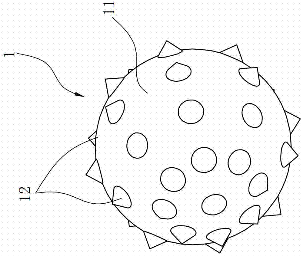
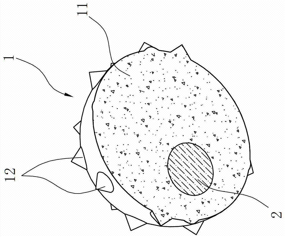
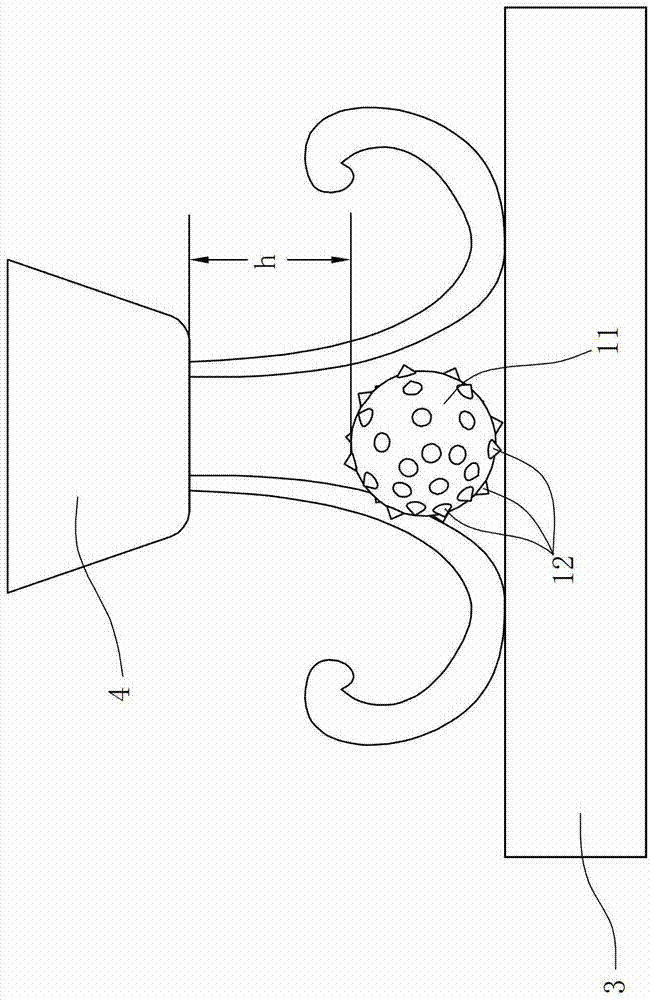
[0030] In order to solve the above problems in the micro-machining process, such as Figure 1 to Figure 8 As shown, the present embodiment proposes a novel cutting device, which includes a particle knife, a cutting workbench 3, a micro-jet nozzle 4 above the workbench 3 and a hydr...


PUM


Abstract

A cutting device is characterized in that the cutting device comprises a particulate knife, a cutting worktable, a micro-jet spray head and a hydraulic device, relative linear movement is achieved between the cutting worktable and the micro-jet spray head, the particulate knife comprises a cutter body and a cutter bit, the cutter bit is arranged on the outer surface of the cutter body in an outward-protruding mode, the geometric dimension of the cutter bit is 10nm-1mm, a balancing weight is arranged in the cutter body, a spray cavity is formed in the micro-jet spray head, a spray mouth is formed in the bottom of the spray cavity, the spray mouth can generate an annular flow, the particulate knife is captured by the annular flow, and the outer diameter of the particulate knife is matched with the inner diameter of the annular flow. The cutting device has the advantages that the particulate knife is driven by water-caused rotation (namely the rotation of micro-jets) or is fixedly clamped to achieve micro-cutting, the micro-flow takes away heat generated during cutting in time, the inhomogeneous deformation field caused by thermomechanical coupling is greatly reduced, quality and working efficiency of micro-cutting are guaranteed, and a novel micro-cutting method is obtained.

Description

technical field [0001] The invention relates to a cutting device, in particular to a cutting device using a particle knife for processing. Background technique [0002] With the development of society, the miniaturization of industrial products has become an important feature of high quality, and the key to realize the transformation of product miniaturization lies in the improvement of the processing technology level of micro parts. [0003] Micro-cutting is a fast and low-cost machining method for tiny parts, and it is not limited by the processing materials. The processing quality of parts (such as precision, surface roughness, etc.) )closely related. The performance of the machine tool is mainly related to the spindle, worktable and control system. The diameter of the tool used in micro-cutting is very small. In order to improve the processing efficiency, the spindle speed of the micro-cutting machine tool is very fast. [0004] In order to meet the torque requirements...

Claims


Application Information

Patent Timeline
Patent Type & Authority Patents(China)
IPC IPC(8): B23D79/00B23Q5/02B23Q11/10
Inventor 程晓民俞友宾周林伍鹏
Owner NINGBO UNIVERSITY OF TECHNOLOGY
Why Eureka
Try Eureka