
Milling method for PCB microgroove formation

A PCB board and milling processing technology, which is applied in the field of milling processing of PCB board micro-groove forming, can solve the problems of difficult to meet the requirements of groove cutter machining life, unstable processing quality, and many groove edge burrs, so as to ensure the processing quality and processing. Efficiency, improve processing efficiency, improve the effect of tool life

Inactive Publication Date: 2018-05-08
SHENZHEN JINZHOU PRECISION TECH
View PDF5 Cites 9 Cited by
  • Summary
  • Abstract
  • Description
  • Claims
  • Application Information

AI Technical Summary

Problems solved by technology

[0002] With the high-speed development trend of electronic system products, the demand for forming fine groove structures for thick PCB boards is gradually increasing. Now groove knives are mainly used to process them, but the length-to-diameter ratio of the groove blades is greater than When it is 10 times, there will be poor groove shape, unstable processing quality, many burrs on the edge of the groove, and the processing life of the groove cutter is difficult to meet the requirements

Method used


Image

  • Milling method for PCB microgroove formation
  • Milling method for PCB microgroove formation
  • Milling method for PCB microgroove formation

Examples


Embodiment Construction

[0044] In order to make the object, technical solution and advantages of the present invention clearer, the present invention will be further described in detail below in conjunction with the accompanying drawings and embodiments. It should be understood that the specific embodiments described here are only used to explain the present invention, not to limit the present invention.

[0045] It should be noted that when an element is referred to as being “fixed on” or “disposed on” another element, it may be directly on the other element or there may be an intervening element at the same time. When an element is referred to as being "connected to" another element, it can be directly connected to the other element or intervening elements may also be present.

[0046] It should also be noted that the orientation terms such as left, right, up, and down in the embodiments of the present invention are only relative concepts or refer to the normal use state of the product, and should ...


PUM


Abstract

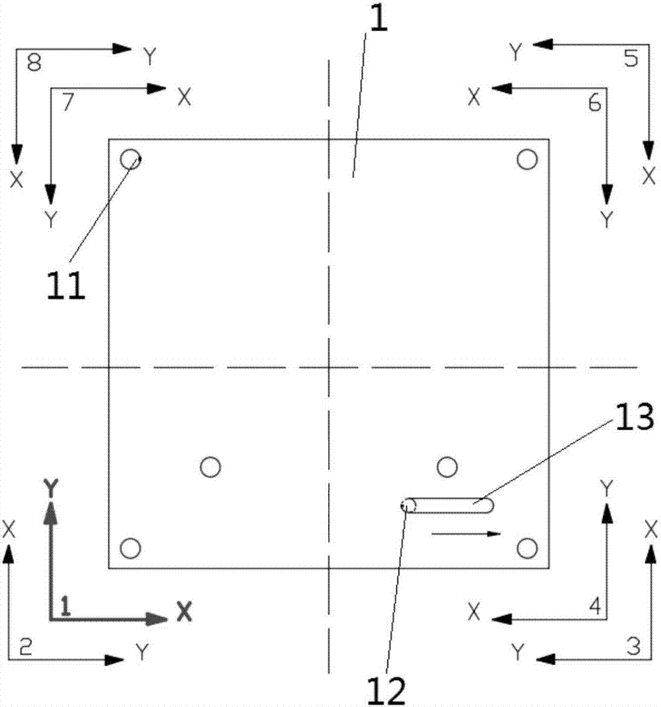
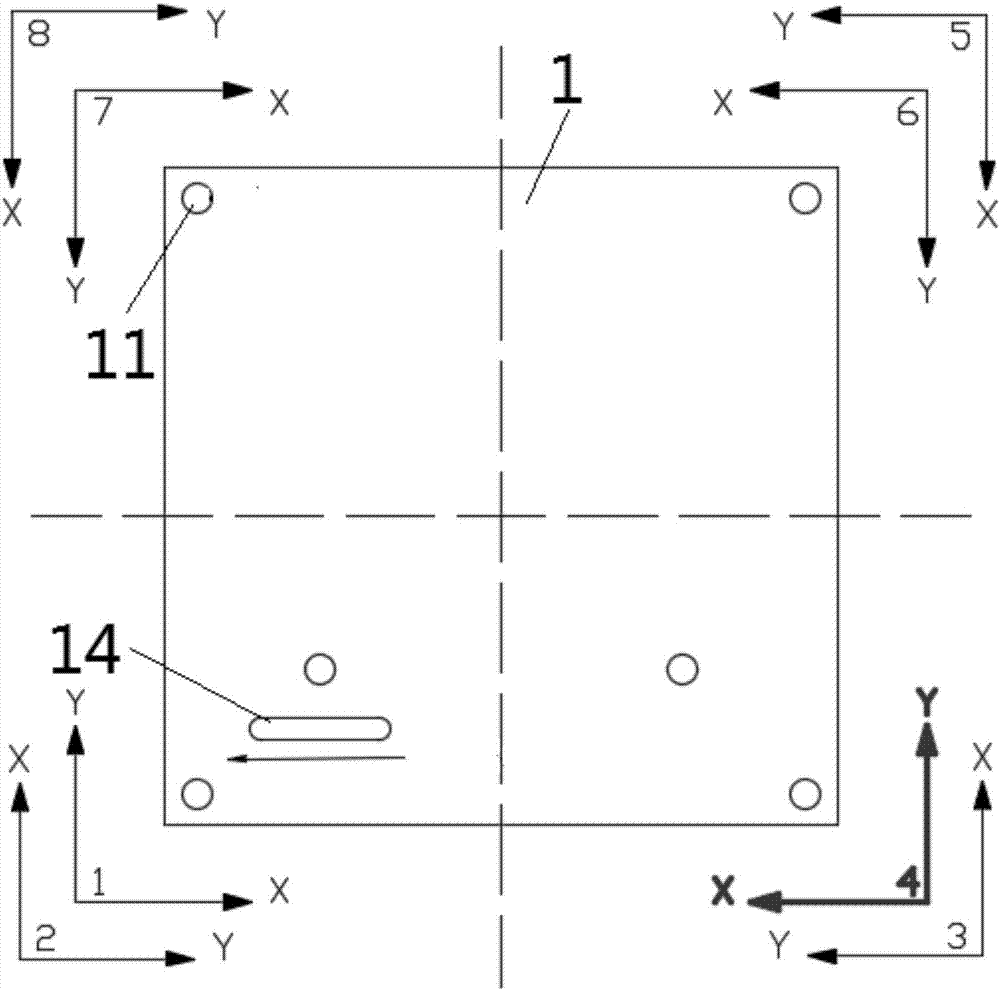
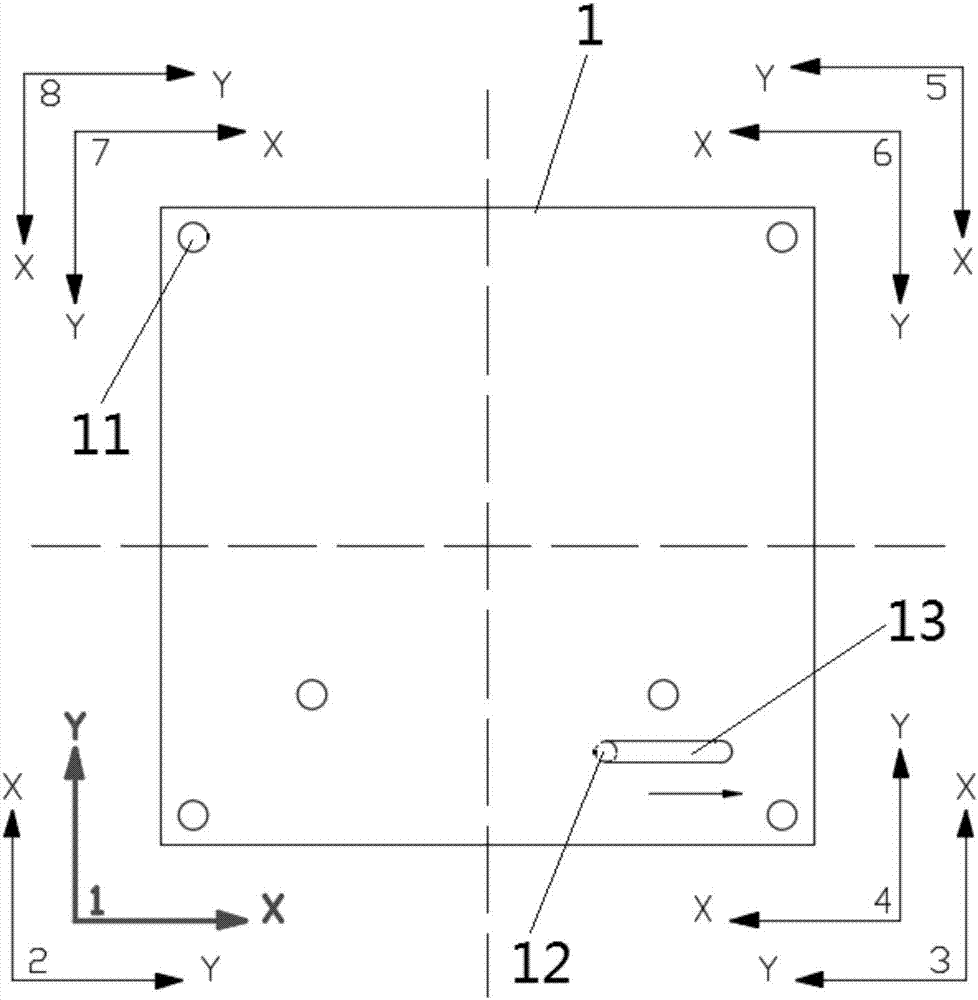
The invention is suitable for the technical field of PCB machining, and discloses a milling method for PCB microgroove formation. The milling method comprises the following steps that the PCB is fixedon the machining position; the cutting hole penetrating through the circuit board is drilled on the PCB by using a drill; a first milling cutter is adopted to cut from the cutting hole and the firstmilling cutter drills to the depth of 0.5-0.7 time of the board thickness of the PCB and then the first milling cutter performs the first time of horizontal milling on the PCB along a first directionaccording to a first path; the PCB after completion of the first time of horizontal milling is overturned and fixed; and a second milling cutter cuts from the end point corresponding to the first pathand the second milling cutter drills to the depth of 0.5-0.7 time of the board thickness of the PCB and then the second milling cutter mills to the start point corresponding to the first path along asecond direction according to the direction opposite to the first path. According to the milling method for PCB microgroove formation, the service life of the cutter can be enhanced under the premiseof guaranteeing enhancement of the groove profile quality through the machining method of two-side milling.

Description

technical field [0001] The invention belongs to the technical field of PCB board processing, and in particular relates to a milling processing method for forming micro grooves of a PCB board. Background technique [0002] With the high-speed development trend of electronic system products, the demand for forming fine groove structures for thick PCB boards is gradually increasing. Now groove knives are mainly used to process them, but the length-to-diameter ratio of the groove blades is greater than When it is 10 times, there will be poor groove shape, unstable processing quality, many burrs on the edge of the groove, and the processing life of the groove cutter is difficult to meet the requirements. Contents of the invention [0003] The purpose of the present invention is to overcome the above-mentioned deficiencies in the prior art and provide a milling method for forming micro-grooves on PCB boards, which has good processing effect and long tool life. [0004] The tech...

Claims


Application Information

Patent Timeline
IPC IPC(8): H05K3/00B23C3/00
CPCH05K3/0044B23C3/00
Inventor 刘洋陈光曾期榜
Owner SHENZHEN JINZHOU PRECISION TECH
Learn More