
Coupler knuckle casting method

A knuckle and mold frame technology, which is applied in the direction of casting molding equipment, casting molds, casting mold components, etc., can solve the problems of long preparation period, increased casting cost, and difficulty in meeting short-term delivery requirements, so as to reduce production costs, The effect of improving production efficiency and shortening the production cycle

Inactive Publication Date: 2009-04-08
CRRC QIQIHAR ROLLING CO LTD
View PDF3 Cites 9 Cited by
  • Summary
  • Abstract
  • Description
  • Claims
  • Application Information

AI Technical Summary

Problems solved by technology

For knuckle production in small batches or trial production of new products, casting tooling made of metal materials will increase casting costs; in addition, the existing casting process is difficult to meet the requirements of short-term delivery due to the long preparation period

Method used


Image

  • Coupler knuckle casting method
  • Coupler knuckle casting method
  • Coupler knuckle casting method

Examples


Embodiment Construction

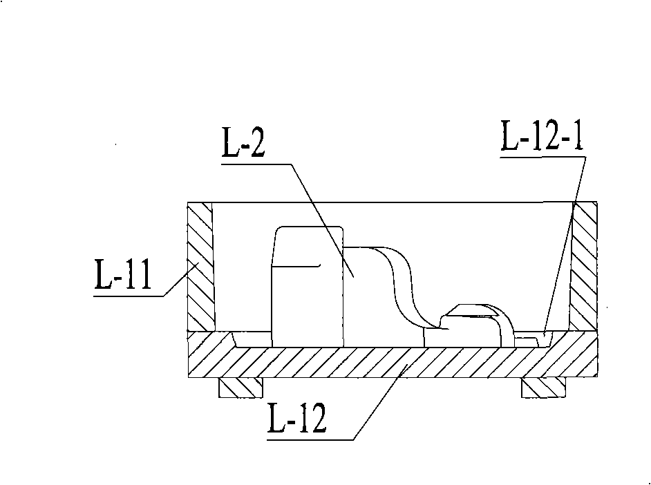
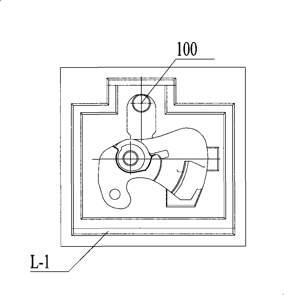
[0044] The following describes the implementation of the present invention in conjunction with the accompanying drawings to describe in detail the technical solutions provided by the present invention; the description in this part is only exemplary and explanatory, and the specific description language or order should not have any influence on the protection scope of the present invention. Limiting effect.

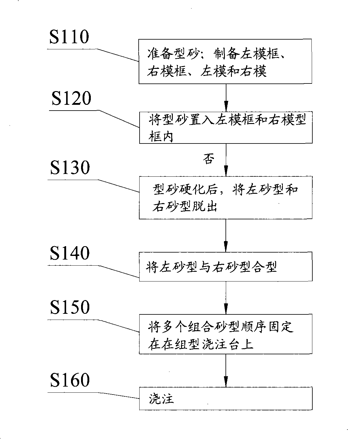
[0045] combine figure 1 , the knuckle casting method provided by Embodiment 1 includes the following steps:

[0046] S110, preparing molding sand; preparing a left mold frame, a right mold frame, a left mold and a right mold.

[0047] Preparation of molding sand is the premise of casting. In this example, ester hardened water glass sand is preferred as molding sand. Since ester hardened water glass sand can be hardened at room temperature and has the characteristics of easy sand falling, it can obtain accurate dimensions and smooth surface. The mold cavity ensures the qu...


PUM


Abstract

The invention discloses a method for casting a coupler knuckle. The method is characterized by realizing boxless shaping by shaping hardened molding sand in a molding frame to obtain left molding sand and right molding sand. During shaping, a left molding frame, a right molding frame, a left mold and a right mold are processed with materials which have low hardness and are easy to process, thereby greatly reducing the difficulty in processing the mold for casting the coupler knuckle, reducing the manufacture cost of casting tools, shortening the preparation period of the casting tools of the coupler knuckle, accordingly reducing the production period for casting the coupler knuckle and making the casting of the coupler knuckle meet the requirements for small-batch production and the process test of new product as well as production requirements on short delivery time.

Description

technical field [0001] The invention relates to a casting technology, in particular to a knuckle casting method of a train coupler buffer device. Background technique [0002] The railway freight car of the wheel-rail vehicle generally includes a car body, a bogie, a brake device, a coupler buffer device and other parts. Among them, the function of the coupler buffer device is to connect the trains, conduct the traction force of the locomotive to make the vehicle run along the track, and bear various loads such as traction and impact caused by the locomotive, car body, and lines. The coupler buffer device is mainly composed of a buffer, a coupler body, a coupler tail frame, a coupler cluster plate and a coupler tongue. Wherein, adjacent trains are connected through the cooperation of knuckle and knuckle. [0003] In recent years, with the rapid development of my country's railway construction and the increase in export products of railway wagons, there are more and more ty...

Claims


Application Information

Patent Timeline
IPC IPC(8): B22C9/02B61G1/36
Inventor 王克明郝施奇孟庆庆
Owner CRRC QIQIHAR ROLLING CO LTD
Learn More