Special composite fixture for clamping shaft collar

A technology of clamps and collars, which is applied in the field of special fixtures for clamping collars, can solve the problems of low universality of special fixtures, difficult control of clamping force, and unreliable clamping, etc. The effect of easy control of force and reliable positioning

Inactive Publication Date: 2013-12-04
WUXI YICHEN MOLD TECH
View PDF6 Cites 7 Cited by
  • Summary
  • Abstract
  • Description
  • Claims
  • Application Information

AI Technical Summary

Problems solved by technology

[0003] Aiming at the problems of unreliable clamping of shaft parts containing collars, difficult control of clamping force and low versatility of special fixtures with existing general fixtures, the present invention provides a special composite fixture for clamping collars

Method used


Image

  • Special composite fixture for clamping shaft collar
  • Special composite fixture for clamping shaft collar
  • Special composite fixture for clamping shaft collar

Examples


Embodiment 1

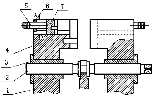
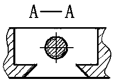
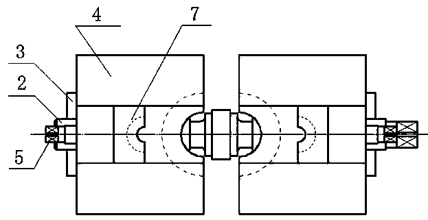
[0020] like figure 1 , figure 2 , image 3 As shown, the special composite fixture for collar clamping includes fixture seat, slide rail 1, large adjusting screw 2, moving block 3, large clamping block 4, small adjusting screw 5, fixed block 6 and small clamping block 7 , the lower end of the slide rail 1 is installed on the fixture seat, the upper end of the slide rail 1 is stuck on the concave edge of the lower end of the moving block 3, the large adjusting screw 2 is engaged with the moving block 3, and the large clamping The lower end of the block 4 is pressed on the concave edge of the upper end of the moving block 3, the upper end of the large clamping block 4 is provided with a groove, the vertical section of the upper part of the groove is rectangular, the lower part of the groove is a dovetail groove, and the fixed block 6 At the side end of the groove of the large clamping block 4, the upper end of the small clamping block 7 is flush with the upper end of the groo...

Embodiment 2

[0023] like figure 1 , figure 2 , image 3 As shown, the special composite fixture for collar clamping includes fixture seat, slide rail 1, large adjusting screw 2, moving block 3, large clamping block 4, small adjusting screw 5, fixed block 6 and small clamping block 7 , the lower end of the slide rail 1 is installed on the fixture seat, the upper end of the slide rail 1 is stuck on the concave edge of the lower end of the moving block 3, the large adjusting screw 2 is engaged with the moving block 3, and the large clamping The lower end of the block 4 is pressed on the concave edge of the upper end of the moving block 3, the upper end of the large clamping block 4 is provided with a groove, the vertical section of the upper part of the groove is rectangular, the lower part of the groove is a dovetail groove, and the fixed block 6 At the side end of the groove of the large clamping block 4, the upper end of the small clamping block 7 is flush with the upper end of the groo...


PUM


Abstract

The invention discloses a special composite fixture for clamping a shaft collar and belongs to the field of machine tool fixtures. The special composite fixture comprises a fixture block, sliding rails, a large adjusting screw, a moving block, a large clamping block, a small adjusting screw, a fixed block and a small clamping block, wherein the lower ends of the sliding rails are arranged on the fixture block; the large adjusting screw is meshed with the moving block; the lower end of the small clamping block is embedded into a dovetail groove in the lower end of a groove of the large clamping block; the small adjusting screw is meshed with the fixed block; one end of the small adjusting screw is fixedly connected with the small clamping block; a clamping surface of the large clamping block and a clamping surface of the small clamping block respectively consist of three semicircular cylindrical surfaces with different diameters; the diameters of the semicircular cylindrical surfaces are identical with the corresponding diameters of workpieces. According to the special composite fixture disclosed by the invention, the problems that shaft parts containing the shaft collars cannot be reliably clamped, a clamping force is not easy to control and a special fixture is not high in generality in the traditional general fixture are solved. The special composite fixture has the advantages of simple structure, reasonable design and easiness in manufacture.

Description

Technical field [0001] The present invention belongs to the field of machine tool fixture. More specifically, it involves a special fixture for holding a shaft. Background technique [0002] In the mechanical manufacturing industry, lathes, especially milling machines, are widely used in processing discs or shaft parts.When processing such parts, many parts need to be cut with end surfaces or inner holes as positioning clamping surfaces for cutting processing such as outer circular, end surface, threads, and axial cutting.For the processing of single -piece, small batch, and large -scale workload, it can generally be directly used to adjust the positioning and clamping by adjusting the position of the machine tools, and then determine the position of the parts through the setting of the coordinate system.For parts with a certain batch, you need to use related special fixtures to reduce labor intensity, reduce parts processing assistance time, and improve production efficiency.Esp...

Claims


Application Information

Patent Timeline
Patent Type & Authority Applications(China)
IPC IPC(8): B23Q3/06
Inventor 钱根来李康魏鑫夏守忠陈微霞丁亭
Owner WUXI YICHEN MOLD TECH
Why Eureka
Try Eureka