Vacuum glass getter placement structure and manufacturing method thereof

A technology of vacuum glass and getter, which is used in glass forming, glass re-forming, glass manufacturing equipment and other directions to achieve the effect of improving heat insulation, high vacuum degree and reliable sealing

Inactive Publication Date: 2013-12-04
戴长虹
View PDF4 Cites 3 Cited by
  • Summary
  • Abstract
  • Description
  • Claims
  • Application Information

AI Technical Summary

Problems solved by technology

[0006] The technical problem to be solved by the present invention is to provide a novel vacuum glass getter placement structure and its manufacturing method in view of the defects in the placement structure of the existing vacuum glass getter. The manufacturing method of the placed structure is simple in process, and the manufactured vacuum glass, including tempered vacuum glass, can overcome the deficiencies in the prior art for placing getters, can effectively ensure the high vacuum degree of the vacuum layer of the vacuum glass, prolong the service life of the vacuum glass, and It can improve the production efficiency of vacuum glass containing getter and reduce the production cost

Method used


Image

  • Vacuum glass getter placement structure and manufacturing method thereof

Examples


Embodiment

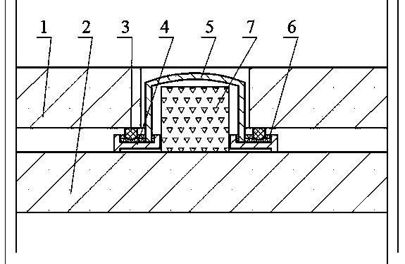
[0044]Embodiment: Referring to the accompanying drawings, the vacuum glass is composed of an upper glass 1 and a lower glass 2. A through hole is drilled on the upper glass 1 to form an air extraction port, and a sealing ring 3 concentric with the air extraction port is made on the lower surface of the upper glass 1. Place an annular sealing box 4 concentric with the air inlet on the upper surface of the glass 2, the sealing ring 3 of the upper glass 1 can be inserted in the annular sealing box 4; according to the size of the annular sealing box 4, make a sealing cover 5 again, the sealing cover The edge portion of 5 can be inserted into the annular sealing box 4, and the height of the sealing cover 5 is lower than the upper surface of the upper glass 1; the upper and lower glasses are tempered, or the upper and lower glasses after being combined in an atmospheric pressure and high temperature furnace are directly used with low temperature glass solder. The glass is edge-sealed...


PUM


Abstract

The invention provides a vacuum glass getter placement structure which is characterized in that punching is performed on an upper piece of glass of vacuum glass to form an extraction opening, a sealing ring is prepared at the periphery of the extraction opening and the lower surface of the upper piece of glass, an annular sealing box is placed on a lower piece of glass, and a sealing cover is further arranged on the annular sealing box; after edges of the upper piece of glass and the lower piece of glass are sealed, the getter is placed into the extraction opening, the extraction opening is covered with the sealing cover, then metal solder is placed into the annular sealing box or on the sealing cover, the extraction opening is vacuumized and heated, the getter is automatically activated at high temperature and under high vacuum, meanwhile metal solder is melted into liquid at high temperature, the liquid is retained in the annular sealing box, edge parts of the sealing ring and the sealing cover are submerged into the liquid, the extraction opening is in self sealing by utilizing the liquid sealing principle and the getter is further sealed in the vacuum layer, and after cooling, the liquid is solidified, and air tightness seal is realized. According to the method provided by the invention, mass production can be realized, production efficiency and qualified rate of the vacuum glass are greatly improved, and production cost is reduced.

Description

technical field [0001] The invention belongs to the field of vacuum glass, and in particular relates to a placement structure of a vacuum glass getter and a manufacturing method thereof. [0002] Background technique [0003] The existing vacuum glass is generally composed of two or three pieces of flat glass. The glass is sealed with low-temperature glass solder around the edges, and there is a tiny support in the middle. A thin layer of 0.1-0.2mm thickness is formed between the two pieces of glass by pumping air. Vacuum layer. Since there is no heat and sound transmission of gas, and the inner surface of the glass can have a transparent low-heat radiation film, the vacuum glass has good heat insulation and sound insulation effects, and is one of the best performance energy-saving glasses. [0004] The key technologies of the existing vacuum glass include: one is edge sealing, the other is the placement of supports, and the third is the acquisition and maintenance of vacu...

Claims


Application Information

Patent Timeline
Patent Type & Authority Applications(China)
IPC IPC(8): C03B23/24C03C27/08
CPCY02P40/57
Inventor 戴长虹
Owner 戴长虹
Why Eureka
Try Eureka