
Novel U-shaped pipe bundle type heat exchanger

A technology of U-shaped tubes and heat exchangers, which is applied in the field of new U-shaped tube bundle heat exchangers, can solve the problems of less arrangement of heat exchange tubes, low utilization rate of tube sheets, and unfavorable heat transfer, etc., so as to improve utilization rate, Improve the effect of short circuit phenomenon and improve heat transfer efficiency

Inactive Publication Date: 2013-12-04
SOUTH CHINA UNIV OF TECH
View PDF4 Cites 2 Cited by
  • Summary
  • Abstract
  • Description
  • Claims
  • Application Information

AI Technical Summary

Problems solved by technology

Due to the limitation of the radius of curvature of the bent tube, the arrangement of heat exchange tubes is less, the innermost tube spacing of the tube bundle is relatively large, the utilization rate of the tube sheet is low, and the shell-side fluid is easy to form a short circuit, which is not good for heat transfer

Method used


Image

  • Novel U-shaped pipe bundle type heat exchanger

Examples


Embodiment 1

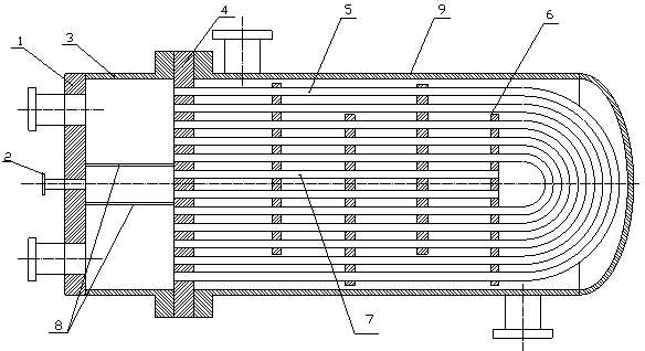
[0020] like Figure 1 As shown, a new type of U-shaped tube bundle heat exchanger includes a guide tube 3, a tube box end cover 1 and a tube plate 4 respectively arranged at the left end and the right end of the guide tube 3, and the right side of the tube plate 4 is fixed There is a U-shaped tube bundle 5 communicating with the guide cylinder 4, and the right side of the tube plate 4 is also connected with a housing 9 that accommodates the U-shaped tube bundle 5 therein, and the housing 9 is also provided with deflectors in parallel. The plate 6 and the guide cylinder 3 are separated by a certain distance at the junction of the inlet and outlet of the U-shaped tube bundle 5. Separate partitions 8 are arranged above and below, and the partitions 8 extend from the tube box end cover 1 to the tube plate 4. In the middle of the tube sheet 4, there is also a straight tube 7 that extends rightward into the innermost cavity of the U-shaped tube bundle 5 and reaches the rightmost baf...


PUM


Abstract

The invention discloses a novel U-shaped pipe bundle type heat exchanger. The novel U-shaped pipe bundle type heat exchanger comprises a flow guide barrel, a pipe box end cover and a pipe plate, wherein the pipe box end cover and the pipe plate are arranged on the left end and the right end of the flow guide barrel respectively; the right side of the pipe plate is fixedly provided with a U-shaped pipe bundle communicated with the flow guide barrel; the right side of the pipe plate is further connected with a shell for containing the U-shaped pipe bundle; the shell is internally provided with U-shaped baffle plates in parallel; pass partition plates are respectively arranged on the upper and lower sides of the crossed parts of inlets and outlets of the U-shaped baffle plates at a certain distance by the flow guide barrel; the pass partition plates extend to the pipe plate from the pipe box end cover; a straight pipe which rightwards stretches into an innermost-layer cavity of a U-shaped pipe bundle to reach the baffle plate on the rightmost side is further arranged in the middle of the pipe plate; and the left end of the straight pipe is communicated with a flow channel surrounded by the pass partition plates. According to the U-shaped pipe bundle type heat exchanger disclosed by the invention, the utilization rate of the pipe plate can be improved by distributing the straight pipe in a non-pipe-distribution space of the innermost layer of the U-shaped pipe bundle, so that a short-circuit phenomenon caused by shell pass fluid due to the larger innermost-layer distance of the pipe bundle is improved and the heat transferring efficiency of the heat exchanger is improved.

Description

[0001] technical field [0002] The invention relates to a new type of U-shaped tube bundle heat exchanger, which can improve the shortcomings of the U-shaped tube bundle heat exchanger, such as the low utilization rate of the tube plate and the short circuit of the shell fluid, and can improve the heat transfer rate of the heat exchanger at the same time. Thermal efficiency. Background technique [0003] The structural feature of the U-shaped tube bundle heat exchanger is that there is only one tube sheet, and the tube bundle is composed of multiple U-shaped tube bundles. The two ends of the tubes are fixed on the same tube sheet, and the tubes can be stretched freely. Due to the limitation of the radius of curvature of the bent tube, the arrangement of heat exchange tubes is less, the innermost tube spacing of the tube bundle is relatively large, the utilization rate of the tube sheet is low, and the shell-side fluid is easy to form a short circuit, which is not good for h...

Claims


Application Information

Patent Timeline
Patent Type & Authority Applications(China)
IPC IPC(8): F28D7/00
Inventor 张龙平张家豪方江敏
Owner SOUTH CHINA UNIV OF TECH
Learn More