Magnetic pole position detecting device

一种磁极位置、检测装置的技术,应用在起动的装置、交流电动机角单轴角速度控制、电气元件等方向,能够解决实用的观点不理想、检测精度降低、无法正确检测磁极位置等问题

Active Publication Date: 2013-12-04
FANUC LTD
View PDF6 Cites 5 Cited by
  • Summary
  • Abstract
  • Description
  • Claims
  • Application Information

AI Technical Summary

Problems solved by technology

[0003] However, in the conventionally known method, the detection accuracy may decrease due to noise contained in the feedback signal, friction acting on the rotor, and external force generated due to load imbalance.
In addition, in the method of moving the rotor to detect the magnetic pole position, the amount of movement of the rotor may increase, which is not preferable from a practical point of view.
In addition, there is a problem that the magnetic pole position cannot be detected correctly when connecting the coil of the motor to the amplifier in the wrong order, setting the number of poles of the motor wrongly, or setting the resolution of the sensor wrongly, etc.

Method used


Image

  • Magnetic pole position detecting device
  • Magnetic pole position detecting device
  • Magnetic pole position detecting device

Examples


Embodiment Construction

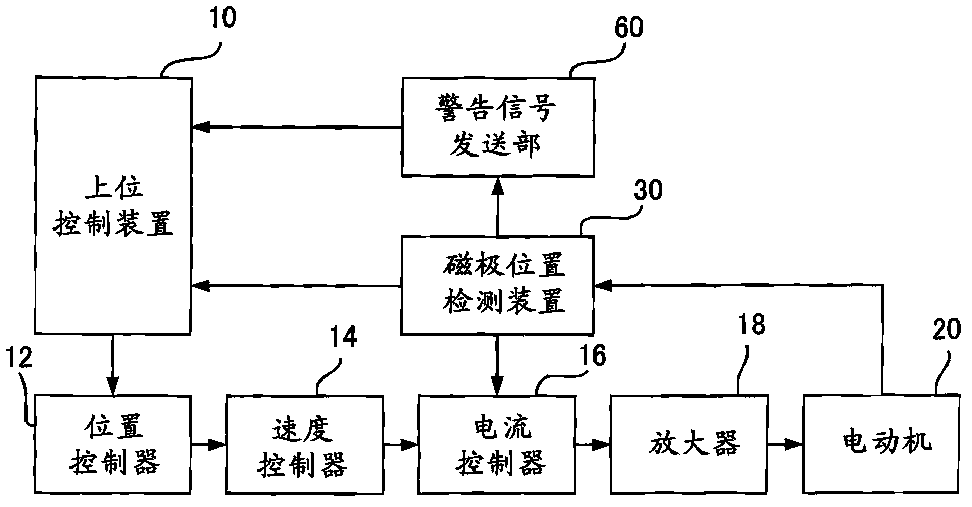
[0015] Hereinafter, embodiments of the present invention will be described with reference to the accompanying drawings. figure 1 It is a block diagram which shows the structure of the control system which can apply this invention. like figure 1 As shown, the control system includes a host controller 10 , a position controller 12 , a speed controller 14 , a current controller 16 , an amplifier 18 , a motor 20 , a magnetic pole position detection device 30 , and a warning signal transmitter 60 . The motor 20 is a known permanent magnet synchronous motor including a rotor provided with permanent magnets and a stator provided with coils. Sensors such as encoders (not shown) for detecting rotor motion (position and speed) are mounted in the motor 20 .

[0016] The host controller 10 controls the operation of the electric motor 20 used for the machine tool or the like. The host control device 10 issues a position command for controlling the operation of each axis of the motor 20 ...


PUM


Abstract

A magnetic pole position detecting device includes a calculating unit for correcting a magnetic pole position detected by a magnetic pole position detecting unit. In this magnetic pole position detecting device, an additional phase is added to the magnetic pole position detected by the magnetic pole position detecting unit, in order to move a rotor. In relation to a movement amount before and after this movement, a movement amount detected by the magnetic pole position detecting unit is compared with a movement amount detected by an encoder. When a difference between them is larger than a predetermined threshold, a process of detecting the magnetic pole position is determined as false detection.

Description

technical field [0001] The present invention relates to a magnetic pole position detection device for detecting the magnetic pole position of a rotor in a permanent magnet synchronous motor. Background technique [0002] In a permanent magnet synchronous motor (hereinafter simply referred to as "motor") including a rotor provided with permanent magnets and a stator provided with coils, a desired torque is obtained by applying current to the coils according to the magnetic pole positions of the rotor. For this purpose, the motor is driven and controlled by applying a current to an appropriate excitation phase while detecting the magnetic pole position of the rotor using a sensor such as an encoder. Therefore, in such a motor, it is necessary to perform position alignment between the reference position of the sensor and the magnetic pole position of the rotor at the time of starting. The method of detecting the magnetic pole position of the rotor for this purpose is described...

Claims


Application Information

Patent Timeline
Patent Type & Authority Applications(China)
IPC IPC(8): H02P6/20H02P6/16H02P23/16H02P23/18H02P27/06
CPCH02P6/18
Inventor 园田直人青地正人
Owner FANUC LTD
Why Eureka
Try Eureka