
Electronic component mounting apparatus

An electronic component installation and electronic component technology, applied in the direction of electrical components, electrical components, etc., can solve the problems of the expansion of the moving area, the deterioration of the efficiency, and the deterioration of the efficiency of the mounted electronic components, so as to suppress the increase in size and production costs. Effect

Inactive Publication Date: 2013-12-04
JUKI CORP
View PDF10 Cites 5 Cited by
  • Summary
  • Abstract
  • Description
  • Claims
  • Application Information

AI Technical Summary

Problems solved by technology

[0009] However, as shown in Patent Document 1, in an electronic component mounting apparatus in which each nozzle replacement section is provided corresponding to each mounting head corresponding to each substrate conveying section, it is necessary to direct the mounting head to the side opposite to each substrate conveying section. Nozzle replacement part movement
Therefore, the moving area of ​​the mounting head is greatly expanded, the efficiency of mounting electronic components on the substrate is deteriorated, and the production cost is increased.
In addition, in the case of an electronic component mounting apparatus in which the mounting head is not moved to the nozzle changer on the opposite side across each substrate conveyance unit, and the moving area of ​​the mounting head is not enlarged, the operating apparatus must be temporarily stopped. The operator manually moves the suction nozzle to each nozzle replacement part
Therefore, also in such an electronic component mounting apparatus, the efficiency of mounting electronic components on the substrate is deteriorated, and the production cost increases.

Method used


Image

  • Electronic component mounting apparatus
  • Electronic component mounting apparatus
  • Electronic component mounting apparatus

Examples


Embodiment Construction

[0054] Hereinafter, preferred modes for implementing the present invention (hereinafter referred to as embodiments) will be described in detail with reference to the drawings. In addition, this invention is not limited by the following embodiment. In addition, each component included in the following embodiments includes configurations that can be easily conceived by those skilled in the art, substantially the same configurations, and configurations within the so-called equivalent range. In addition, components disclosed in the following embodiments may be appropriately combined.

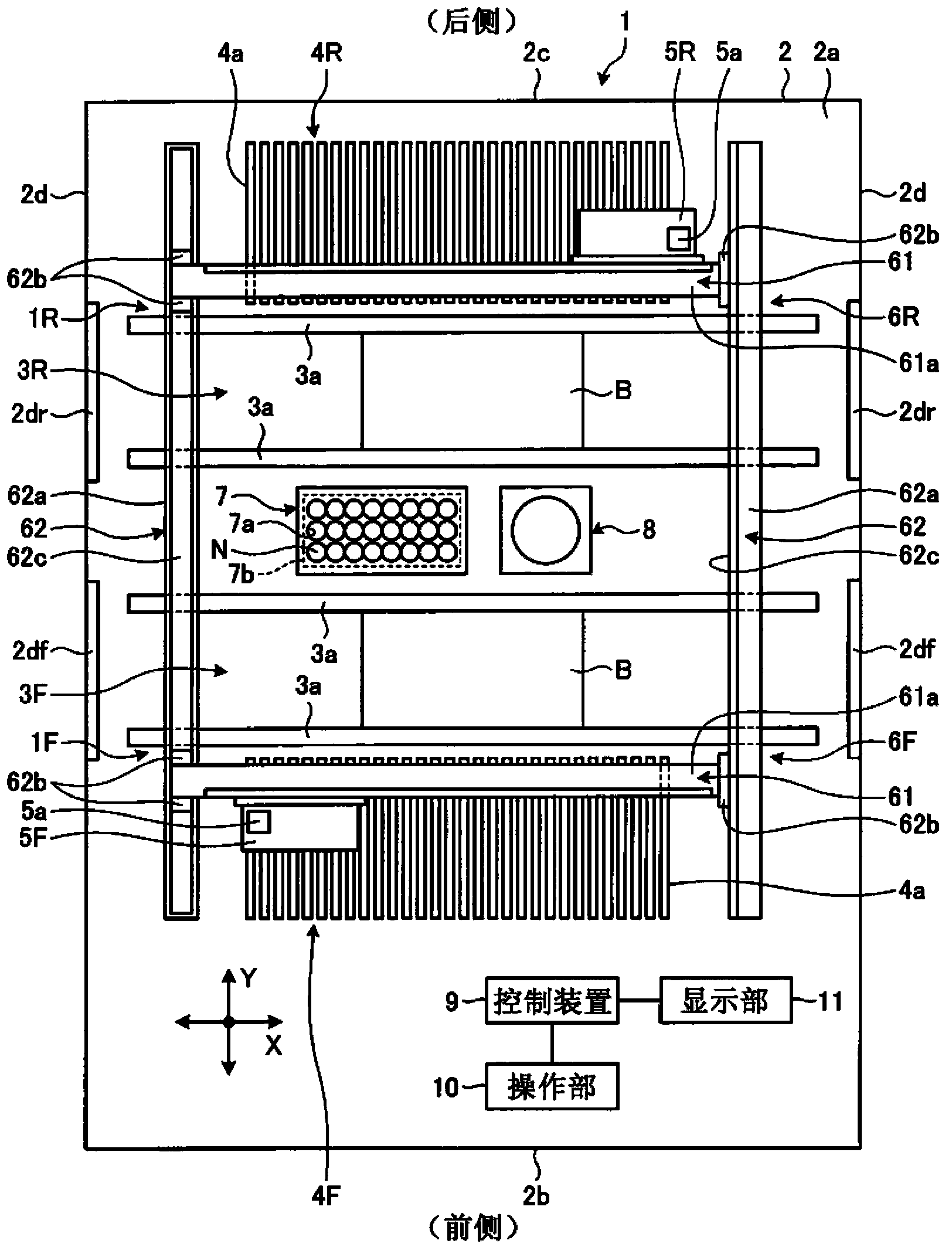
[0055] figure 1 It is a schematic plan view showing the schematic configuration of the electronic component mounting apparatus 1 according to the embodiment of the present invention.

[0056]The electronic component mounting apparatus 1 is an apparatus for mounting electronic components on the board B. As shown in FIG. The electronic component mounting apparatus 1 is arranged on the frame body 2:...


PUM


Abstract

The present invention provides an electronic component mounting apparatus based on the replacement of the common nozzle of the adsorption suppressing increase in size and production cost of the entire device. In the substrate for mounting an electronic component (B) on the electronic component mounting apparatus (1) comprising: a plurality of substrate transfer unit (3F, 3R), it will transport the substrate (B) is arranged parallel to the substrate conveyor line; more mounting head (5F, 5R), which is detachably attached to the electronic component for attracting and holding the adsorption nozzle (N), is set to, can be adsorbed by the suction nozzle (N) to the adsorption of the electronic component held by the substrate transfer unit (3F, 3R) mounted substrate moves; replacement unit and multiple nozzle (7), which is disposed between the substrate conveying portion (3F, 3R), can be placed in different types of adsorbing and holding the electronic components were replaced with a adsorption nozzle (N).

Description

technical field [0001] The present invention relates to an electronic component mounting device that holds an electronic component with a suction nozzle, moves the electronic component, and mounts the electronic component on a substrate. Background technique [0002] Generally, an electronic component mounting apparatus for mounting electronic components on a substrate includes a mounting head having a suction nozzle for holding the electronic component by the suction nozzle and mounting the electronic component on the substrate. The electronic component mounting apparatus moves the suction nozzle of the mounting head in a direction perpendicular to the surface of the substrate to suction the components located in the electronic component supply section, and then makes the mounting head face to face in a direction parallel to the surface of the substrate. to move. Then, after reaching the mounting position of the suctioned component, the suction nozzle of the mounting head ...

Claims


Application Information

Patent Timeline
IPC IPC(8): H05K13/04
Inventor 小浜次郎福泽英浩
Owner JUKI CORP
Learn More