
Precision milling cutter and processing method thereof

A milling cutter, precision technology, applied in the field of processing tools, can solve the problems of milling cutters prone to breakage, cutting edge not sharp enough, and reduce processing efficiency, so as to achieve smooth chip discharge, improve milling cutter strength, and reduce cutter breakage rate Effect

Active Publication Date: 2013-12-11
SHENZHEN JINZHOU PRECISION TECH
View PDF5 Cites 4 Cited by
  • Summary
  • Abstract
  • Description
  • Claims
  • Application Information

AI Technical Summary

Problems solved by technology

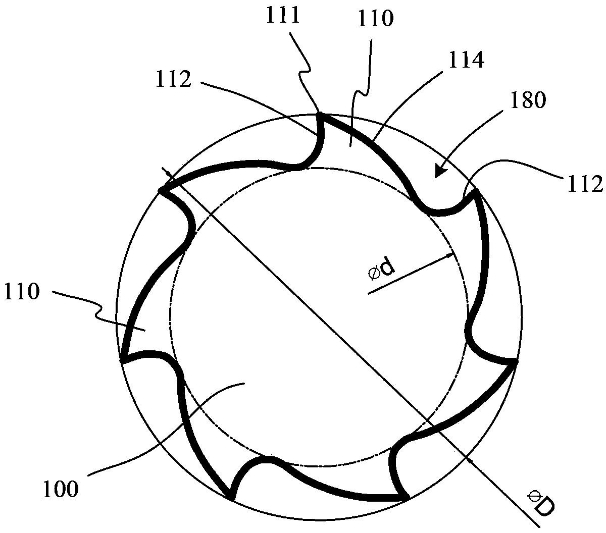
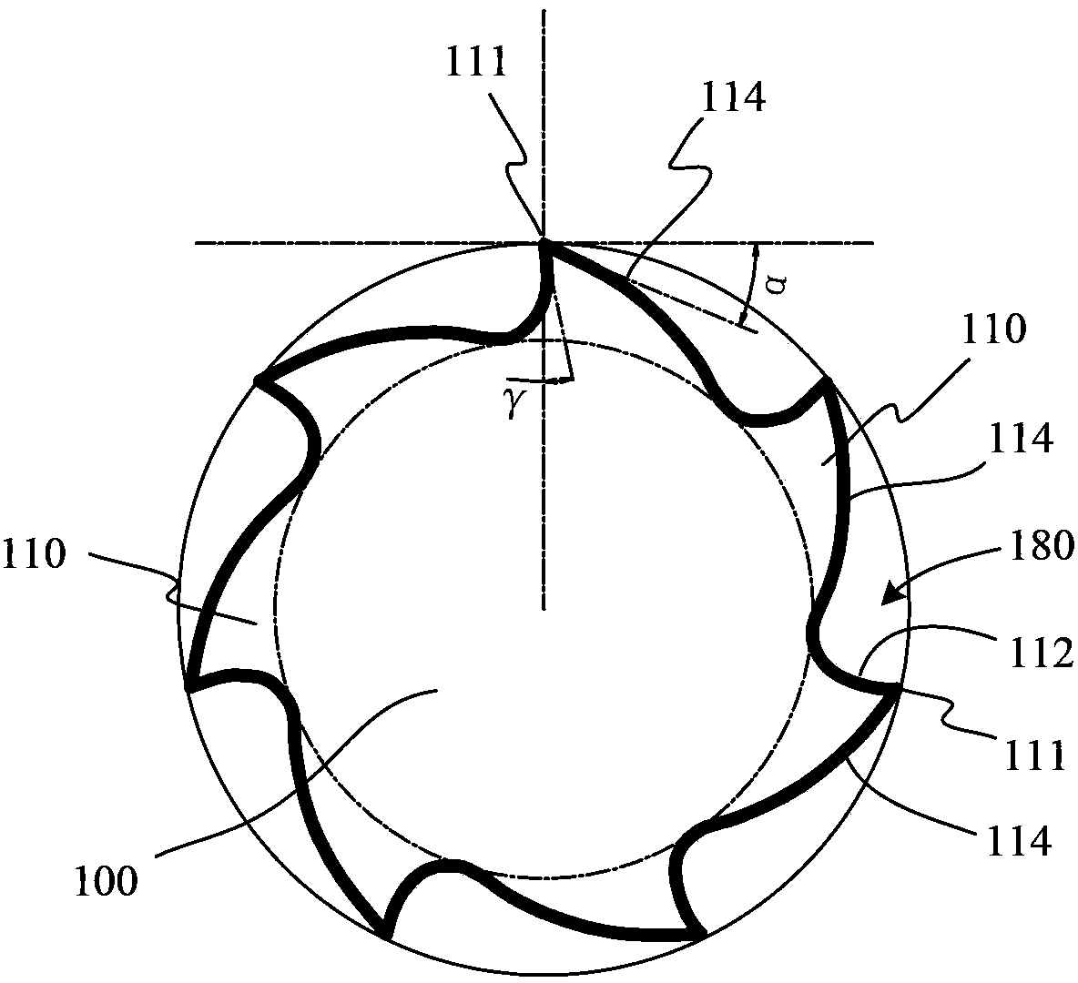
After determining the number of teeth 110 or blade 111, as figure 1 and figure 2 As shown, in order to ensure the sharpness of the tool, the rake angle 112 angle γ must be determined, but in this case, the rear angle α, the chip removal space (and the spiral groove 180) and the core diameter are restricted and cannot be freely adjusted
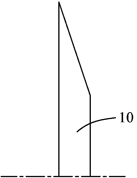
Therefore, this kind of milling cutter has a small chip removal space, the cutting edge is not sharp enough, and the core diameter is limited by the design of the grinding wheel 10, so that the milling cutter is prone to breakage during the milling process, resulting in a short life of the milling cutter, thereby increasing Processing costs and reduced processing efficiency

Method used


Image

  • Precision milling cutter and processing method thereof
  • Precision milling cutter and processing method thereof
  • Precision milling cutter and processing method thereof

Examples


Embodiment Construction

[0028] The present invention will be further described below in conjunction with the accompanying drawings and preferred embodiments.

[0029] Such as Figure 4-6 As shown, the present invention is described with a multi-edge chipbreaker type precision milling cutter, which includes: a cutter body 100 and a plurality of cutter teeth 110 arranged on the outer periphery of the cutter body 100; wherein the cutter teeth 110 include a cutting edge 111, a front cutter Surface 112 and flank surface 114; a flat section is arranged between the cutter teeth 110, forming a flat bottom surface 117 on the cutter body 100, and the rake surface 112 and the cutter surface 114 between adjacent two cutter teeth 110 And the flat bottom surface 117 constitutes the wall surface of the spiral groove 180 respectively, the flat bottom surface 117 makes the bottom of the spiral groove 180 between the knife teeth 110 form a relatively flat bottom surface, the flat bottom surface 117 and the spiral groo...


PUM

PropertyMeasurementUnit
Diameteraaaaaaaaaa

Abstract

The invention discloses a precision milling cutter and a processing method thereof. The milling cutter comprises a cutter body and a plurality of cutter teeth at the periphery of the cutter body, wherein a flat section is arranged between every two cutter teeth to form a flat bottom surface on the bottom of a spiral groove between the two cutter teeth, the flat bottom surfaces and the spiral grooves are arranged on the cutter body according to the same helical angle, and all points on the flat bottom surfaces are equally far away from an axis of the milling cutter. According to the precision milling cutter, by virtue of the flat sections, the distance between every two cutter teeth increases, so that a chip removal space of the milling cutter is enlarged, and chips can be discharged smoothly. By virtue of the flat sections, the distance between every two cutter teeth increases, so that rake angles of cutting edges can be large to allow the cutting edges to be sharp, while back angles of the cutting edges can be reduced correspondingly to ensure the thickness of the cutter teeth so as to avoid tooth breakage. Moreover, by virtue of the flat sections, the bottoms of the spiral grooves are flattened, so that the core diameter of the milling cutter can be enlarged to improve the strength of the milling cutter, and further, the rate of cutter breakage can be lowered.

Description

technical field [0001] The invention relates to the field of processing tools, more specifically, to a precision milling cutter and a processing method thereof. Background technique [0002] Precision milling cutters are generally used for precision machining and manufacturing of various parts, and their machining accuracy is generally high. Taking the processing of PCB as an example, the PCB milling cutter is a cutting tool in the process of milling the shape (forming). [0003] Such as figure 1 and figure 2 As shown, taking the multi-blade chipbreaker milling cutter produced and used at home and abroad as an example, the multi-blade chipbreaker milling cutter includes: a cutter body 100 and cutter teeth 110 arranged on the periphery of the cutter body, and the cutter teeth 110 The space between them is a spiral groove 180, wherein the cutter tooth 110 includes a cutting edge 111, a rake surface 112 and a flank surface 114, and the rake surface 112 and the flank surface...

Claims


Application Information

Patent Timeline
IPC IPC(8): B23C5/08B23C5/00B32B33/00B24B3/12
Inventor 李树源屈建国
Owner SHENZHEN JINZHOU PRECISION TECH
Learn More