
Grinding device with quick-disassembly structure

A grinding and grinding head technology, which is applied to the device for fixing the grinding wheel, the parts of the grinding machine, and the grinding/polishing equipment, etc. The loading and unloading process is simple and practical, the maintenance and replacement are convenient, and the effect of quick and safe removal

Inactive Publication Date: 2013-12-11
JIANGSU HAIJIAN
View PDF6 Cites 4 Cited by
  • Summary
  • Abstract
  • Description
  • Claims
  • Application Information

AI Technical Summary

Problems solved by technology

[0003] Known Velcro closures can consist of a material with a plurality of small hooks, similar to Velcro, wherein known cooperating means can be constructed of a wool-like material with a plurality of small loops, and these known connection means have the following disadvantages : It is easy to wear rapidly with frequent use, and it is easy to cause damage and destruction of the device when it is connected separately, and it is easy to produce attached particles, which causes damage to the wear process of the worn tool, and the connection device loses its original connection force. Leads to increasingly unacceptable connections and, due to frequent reuse of attachments, high maintenance and replacement costs
[0004] Furthermore, the known Velcro closures are generally cumbersome and expensive to produce since the two attachment parts require different materials and manufacturing processes

Method used


Image

  • Grinding device with quick-disassembly structure
  • Grinding device with quick-disassembly structure
  • Grinding device with quick-disassembly structure

Examples


Embodiment Construction

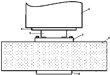
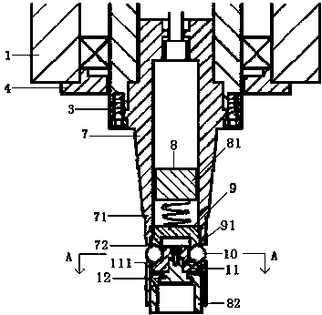
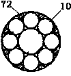
[0027] see Figure 1-4 , shows the grinding device with quick release structure of the present invention.

[0028] Described grinding device comprises the grinding head 1 that is arranged on the front end of grinding machine tool and the grinding cutter 2 that is installed on the grinding head 1 detachably, and described grinding cutter 2 can be diamond grinding head, and described grinding A driving rod 3 is arranged in the grinding head 1, and the driving rod 3 is rotatably placed inside the grinding head 1 and driven to rotate by a driving device (not shown). Between the driving rod 3 and the grinding head 1 Be provided with bearing and locating ring 4, refer to figure 2 , the positioning ring 4 positions the bearing between the driving rod 3 and the grinding head 1 .

[0029] see figure 2 , showing the specific structure of the drive rod 3, the drive rod has a hollow through hole, a knife rod 7 is fixed in the hollow through hole, and the knife rod 7 is fixed by a fla...


PUM


Abstract

The invention discloses a grinding device with a quick-disassembly structure. The grinding device comprises a grinding head and a grinding cutter, wherein a driving rod is arranged in the grinding head; a cutter bar is arranged in the driving rod and comprises a cutter bar body, and a plurality of through holes are formed in the front end of the cutter bar body along the circumference; a locking device is arranged in the cutter bar and comprises an upper locking piece and a lower locking piece; an accommodating space is reserved between the upper locking piece and the lower locking piece; a plurality of balls are arranged in the accommodating space; an upper fixing ring is arranged in a middle hole of the grinding cutter; a tapered hole matched with the cutter bar is formed in the upper fixing ring; an annular limiting bulge is arranged in the middle of the tapered hole; and an annular positioning groove matched with the balls is formed below the limiting bulge. The grinding device can realize quick connection and disassembly between the cutter and the grinding head, is difficult to wear, can save more space, is convenient to maintain, saves the cost, and improves the efficiency.

Description

technical field [0001] The invention relates to the technical field of grinding accessory mechanisms, in particular to a grinding device with a quick-release structure. Background technique [0002] Various grinding devices are known in grinding technology for the detachable connection of exchangeable grinding elements, in particular grinding blades, grinding heads etc. In circular grinding machines, for simple and rapid replacement and maintenance of the grinding tools, the prior art can be used on the top surface of the receiving body, for example formed by the grinding disc, as well as in the grinding tool in the form of flat hook and loop fasteners. Attachment connectors arranged in pairs to allow for an easily releasable connection. [0003] Known Velcro closures can consist of a material with a plurality of small hooks, similar to Velcro, wherein known cooperating means can be constructed of a wool-like material with a plurality of small loops, and these known connect...

Claims


Application Information

Patent Timeline
Patent Type & Authority Applications(China)
IPC IPC(8): B24B45/00
Inventor 于旺江王金东胡斌胡文忠周斌
Owner JIANGSU HAIJIAN
Learn More