Piezoelectric type jet nozzle device for micro-droplet generation

A piezoelectric and micro-droplet technology, which is applied in printing and other directions, can solve the problems of limiting the jetting frequency of piezoelectric jetting devices, taking a certain amount of time to arrive, and the high cost of commercialized jetting heads, so as to reduce jetting waiting time and facilitate The effect of production and improvement of service life

Active Publication Date: 2013-12-11
ZHEJIANG UNIV
View PDF11 Cites 23 Cited by
  • Summary
  • Abstract
  • Description
  • Claims
  • Application Information

AI Technical Summary

Problems solved by technology

The commercial nozzles produced by this method are expensive and not easy to disassemble and wash. Once the nozzles are blocked, the whole device cannot be used again, causing serious waste, and the produced nozzles are suitable for low-viscosity liquids, not high-viscosity liquids.
[0007] In addition, in the existing piezoelectric injection device, due to the influence of the liquid in the pelvic cavity, after the piezoelectric ceramic sends out a pressure wave, it takes a certain amount of time to reach the nozzle.
Moreover, in order to avoid the influence of the follow-up pressure wave on the previous pressure wave, it is necessary to completely attenuate the previous pressure wave before sending the subsequent pressure wave, which requires a long waiting time between two adjacent drops, which greatly limits the piezoelectric Injection frequency of injection device

Method used


Image

  • Piezoelectric type jet nozzle device for micro-droplet generation

Examples


Embodiment Construction

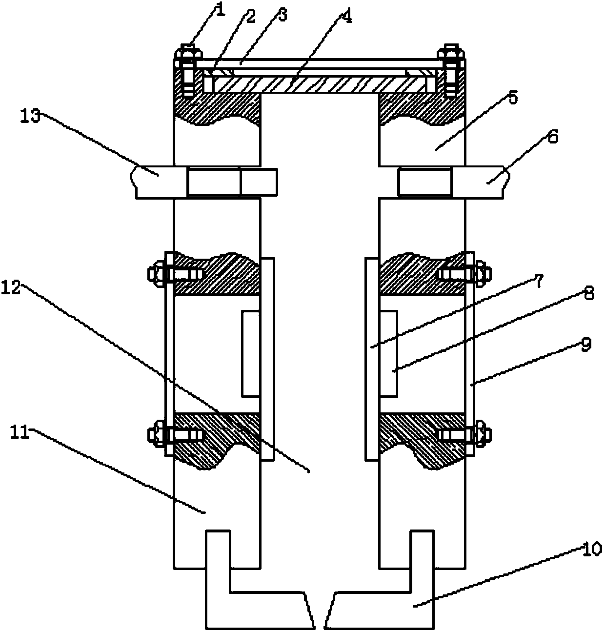
[0027] Such as figure 1 As shown, a novel piezoelectric nozzle device for micro-droplet generation, including: an injection body with an injection chamber 12, a nozzle 10 located at one end of the injection body, an injection power source, a pressure detection mechanism, and a pressure wave attenuation mechanism Wait.

[0028] The injection cavity 12 is a cylindrical structure, including an upper cavity 5 and a lower cavity 11; the upper cavity 5 and the lower cavity 11 are fixed to each other by a coaxial annular connecting plate 9, that is, the top of the connecting plate 9 is connected to the The bottom of the upper cavity 5 is fixed, and the bottom end of the connecting plate 9 is fixed to the top of the lower cavity 11 by studs. There is a gap for placing the piezoelectric ceramic ring 8 between the two fixed ends of the upper cavity 5 and the lower cavity 11 . The top of the upper chamber 5 is provided with a mounting groove for arranging the piezoelectric diaphragm 4 ...


PUM


Abstract

The invention discloses a piezoelectric type jet nozzle device for micro-droplet generation. The piezoelectric type jet nozzle device comprises a jet body, a jet nozzle, a piezoelectric diaphragm, a pressure sensor and a pressure wave attenuation mechanism. The jet body is provided with a jet cavity, the jet nozzle is arranged at one end of the jet body, the piezoelectric diaphragm is arranged on the jet body and used for providing jet power, the pressure sensor is used for detecting change of fluid pressure in the jet cavity and outputting collected pressure signals, and the pressure wave attenuation mechanism is used for transmitting attenuation pressure waves used for attenuating residual pressure waves in the jet cavity according to the received pressure signals. According to the piezoelectric type jet nozzle device, the pressure sensor and the pressure wave attenuation mechanism work in cooperation with each other, change conditions of pressure waves in the jet cavity are detected in real time through the pressure sensor, the residual pressure waves in the jet cavity are quickly attenuated through the pressure wave attenuation mechanism under the premise of guaranteeing normal jet operation, therefore, jet waiting time is shortened, and jet frequency is improved.

Description

technical field [0001] The invention relates to the field of droplet ejection, in particular to a piezoelectric spray head device for generating a droplet. Background technique [0002] Droplet jetting technology is a new type of rapid prototyping technology, which has developed rapidly in the last 20 years. According to the different injection methods, it can be divided into two types: continuous inkjet and drop-on-demand inkjet. Among them, compared with continuous spraying, on-demand spraying has the advantages of controllable droplet size, high deposition accuracy and resolution, and good reliability, so it has high commercial development potential. [0003] At present, in the application of on-demand injection, there are several technologies as follows: 1. Thermal bubble injection technology (US patent document US8100495B2, named Inkjet Printhead); 2. Piezoelectric injection technology (US patent document US7909438B2, named Inkjet Printhead); Piezo-electric Type Inkje...

Claims


Application Information

Patent Timeline
Patent Type & Authority Applications(China)
IPC IPC(8): B41J2/045B41J2/14
Inventor 贺永魏子渊傅建中吴森洋薛光怀
Owner ZHEJIANG UNIV
Why Eureka
Try Eureka