Special lifting device for shaft roller

A hoisting device and shaft-roller technology, which is applied in hoisting devices, hoisting equipment braking devices, cranes, etc., can solve problems such as high labor intensity, low production efficiency, and poor product quality, and achieve flexible spreader angles and convenient operation Effect

Inactive Publication Date: 2013-12-11
天津普罗菲特纺织有限公司
View PDF2 Cites 2 Cited by
  • Summary
  • Abstract
  • Description
  • Claims
  • Application Information

AI Technical Summary

Problems solved by technology

[0003] There are four major problems: low production efficiency, po

Method used


Image

  • Special lifting device for shaft roller
  • Special lifting device for shaft roller
  • Special lifting device for shaft roller

Examples


Embodiment Construction

[0019] The present invention will be described in detail below in conjunction with the accompanying drawings.

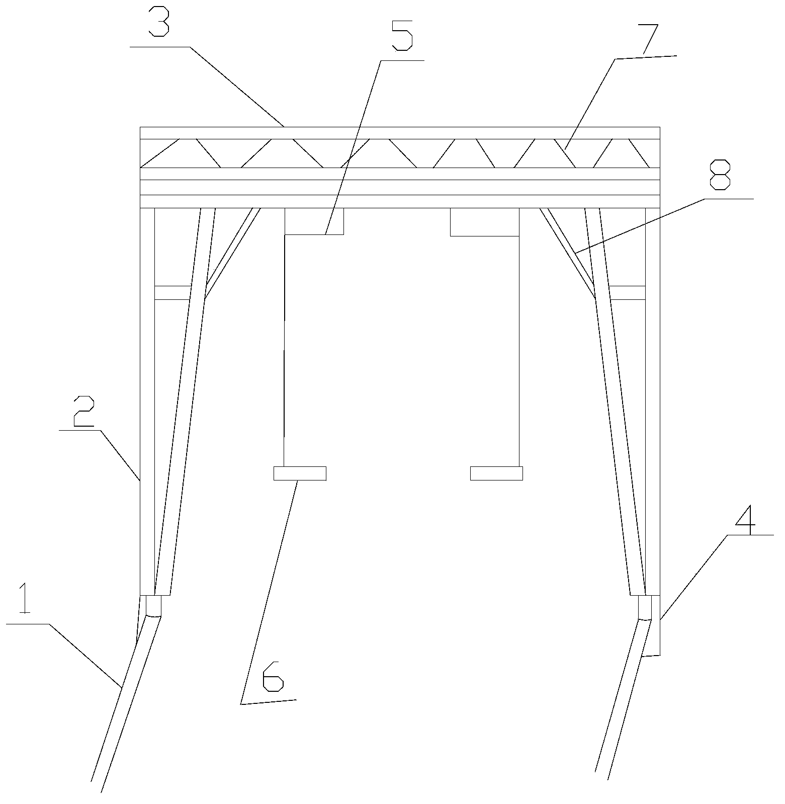
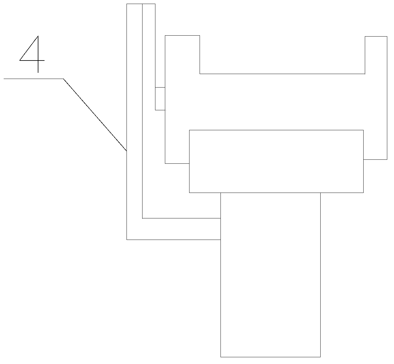
[0020] Such as figure 1 , 2 As shown, the present invention is a special hoisting device for shaft rollers, including two rails 1, a hoisting frame and a hoisting device; the hoisting frame is composed of two moving mechanisms 2 and a beam 3, and the bottom of the moving mechanism 2 is provided with The roller used in conjunction with the track 1 is provided with an anti-derailment structure 4 on the outside of the roller; the lifting device is composed of an electric hoist 5 and a lifting tool 6, and the bottom end of the wire rope on the electric hoist 5 is provided with a lifting tool 6, and the lifting device is provided with There are two parts, and the lifting device is controlled by an electric control switch.

[0021] The crossbeam 3 is provided with a reinforcing rod 7, the moving mechanism 2 and the crossbeam 3 are provided with a fixed rod 8, and the hoi...


PUM


Abstract

The invention provides a special lifting device for a shaft roller, which comprises two rails, a hoisting frame and lifting device parts, wherein the hoisting frame consists of two moving mechanisms and a cross beam; the lifting device parts consist of electric hoists and hoisting tools; and the hoisting frame consists of hollow steel tubes. The special lifting device has the benefits that the special lifting device is simple in structure, simple to operate, small in floor area, and flexible in hoisting tool angle.

Description

technical field [0001] The invention belongs to the field of hoisting devices, in particular to a special hoisting device for a shaft and roller. Background technique [0002] The Italian carding machine used by this enterprise is a large-scale equipment in the textile industry. In the process of using 45 "needle rollers" to hang wool, it takes 2-3 days to do a cleaning (brushing); after a period of production of the needle rollers, the needles on the rollers are not sharp, which affects the combing effect. Grinding needles. All of these need to be manually lifted up and down the "needle roller", and the heaviest is more than 300 kilograms. [0003] There are four major problems: low production efficiency, poor product quality, high labor intensity, and high degree of danger. Contents of the invention [0004] The object of the present invention is to provide a special hoisting device for shaft and roller with simple structure, simple operation and improved loading and ...

Claims


Application Information

Patent Timeline
IPC IPC(8): B66C19/00B66C5/02B66C6/00
Inventor 胡晓毅
Owner 天津普罗菲特纺织有限公司
Why Eureka
Try Eureka