Automatic lifting control device of fan

A technology of automatic lifting and control devices, applied in pump control, machine/engine, non-variable pumps, etc., can solve the problems of resource waste and inconvenience

Inactive Publication Date: 2013-12-11
庄景阳
View PDF6 Cites 6 Cited by
  • Summary
  • Abstract
  • Description
  • Claims
  • Application Information

AI Technical Summary

Problems solved by technology

[0002] The height adjustment of the current desktop fan is manual, which is inconvenient, especially in summer, when sleeping at night, many people like to sleep on the floor, and when the fan is at a high position, it cannot cool down the people who are resting well. You have to buy another fan with the frame directly on the fan head, which leads to a waste of resources

Method used


Image

  • Automatic lifting control device of fan
  • Automatic lifting control device of fan

Examples


Embodiment Construction

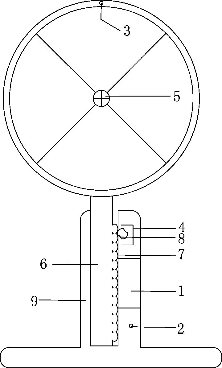
[0012] figure 1 It is a schematic diagram of the descending of a fan automatic lifting control device according to the present invention,

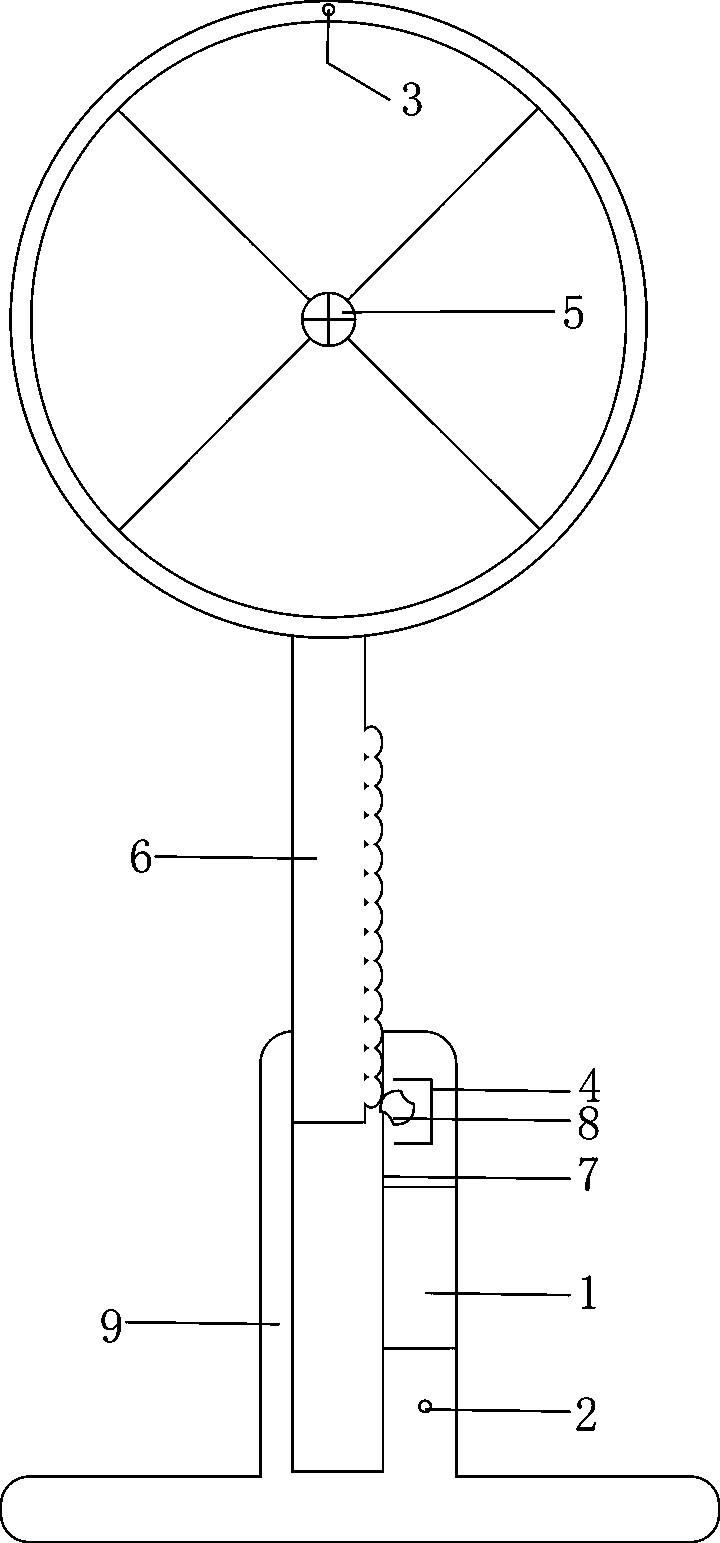
[0013] figure 2 It is a rising schematic diagram of a fan automatic lifting control device of the present invention.

[0014] The present invention is composed of: control module 1, No. 1 sensor 2, No. 2 sensor 3, lifting motor 4, fan motor 5, lifting rod 6, rack gear 7, runner 8, base 9, and clock 10. exist figure 1 , figure 2 Among them, the No. 1 pin of the control module 1 is connected to the No. 1 sensor 2, the No. 2 pin of the control module 1 is connected to the No. 2 sensor 3, the No. 3 pin of the control module 1 is connected to the signal line of the clock 10, and the power supply of the control module 1 A power plug with a wire is drawn from the input end, the No. 1 output end of the control module 1 is connected with the lift motor 4 , and the No. 2 output end is connected with the fan motor 5 .

[0015] The detection ra...


PUM


Abstract

The invention discloses an automatic lifting control device of a fan. The automatic lifting control device comprises a control module, a sensor I, a sensor II, a lifting motor, a fan motor, a lifting rod, row teeth, a turning wheel, a base and a clock, and the automatic lifting control device is characterized in that a pin I of the control module is connected with the sensor I; a pin II of the control module is connected with the sensor II, and a pin III of the control module is connected with a signal line of the clock; a power plug with a line is led out of the power source input end of the control module, the output end I of the control module is connected with the lifting motor, and the output end II of the control module is connected with the fan motor. The automatic lifting control device provided by the invention has the beneficial effects that the automatic lifting control device of the fan has the function of automatically adjusting the power of the fan and lifting the fan to a high / low position according to the standing or laying posture of a person.

Description

technical field [0001] The invention relates to a control technology capable of automatically controlling the height and rotation speed of a fan according to the position of a person, in particular to an automatic lifting control device for a fan. Background technique [0002] The height adjustment of the current desktop fan is manual, which is inconvenient, especially in summer, when sleeping at night, many people like to sleep on the floor, and when the fan is located at a high position, it cannot cool down the people who are resting well. It is necessary to buy another fan with the fan head directly attached to the frame, resulting in a waste of resources. Contents of the invention [0003] The purpose of the present invention is to provide a fan automatic lifting control device, which can automatically adjust the power of the fan and the height of the fan according to the position of the person standing or lying down. [0004] The present invention is realized by the ...

Claims


Application Information

Patent Timeline
Patent Type & Authority Applications(China)
IPC IPC(8): F04D27/00
Inventor 庄景阳
Owner 庄景阳
Why Eureka
Try Eureka