Intelligent gear
A gear and intelligent technology, applied in the direction of belts/chains/gears, components with teeth, portable lifting devices, etc., can solve the problems of difficult sensor arrangement and installation, complex environment, dynamic data acquisition and status monitoring of transmission devices, etc. Achieve the effect of solving dynamic data collection
- Summary
- Abstract
- Description
- Claims
- Application Information
AI Technical Summary
Problems solved by technology
Method used
Image
Examples
Embodiment 1
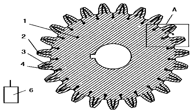
[0051] Such as figure 1 Shown is a schematic structural diagram of the smart gear embodiment 1 of the present invention. An intelligent gear in this embodiment includes a gear body 1 and a monitoring device for real-time monitoring of the working condition of the gear body, and the gear body 1 is provided with gear teeth and tooth grooves;
[0052] The tooth is provided with cogging, and the cogging includes two curved coggings 3 that are equidistant from the tooth profile of the tooth and the intersection point between the top of the tooth and the two curved coggings 3 Between and in the linear gear tooth groove 2 in the radial direction of the gear body 1 . A gear groove 4 is arranged in the tooth groove, and the gear groove 4 includes a linear gear groove symmetrically arranged in the tooth groove and located in the radial direction of the gear body 1 . The gear groove 4 of this embodiment also includes a round hole groove arranged at the end of the linear gear groove clo...
Embodiment 2
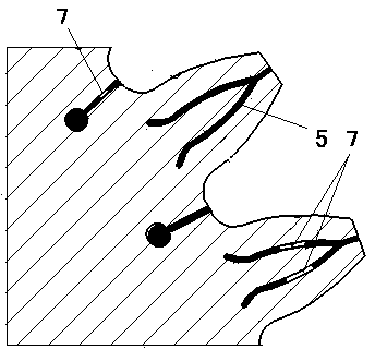
[0078] Such as Figure 11 Shown is a schematic structural diagram of the smart gear embodiment 2 of the present invention. The smart gear of this embodiment includes a gear body 1 and a monitoring device for monitoring the working condition of the gear body in real time. The gear body 1 is provided with gear teeth and tooth grooves. The gear tooth is provided with a gear groove, and the gear groove includes two curved gear grooves 3 that are equidistant from the tooth profile of the gear tooth, and is arranged at the intersection point of the tooth top of the tooth and the two curved gear grooves 3 Between the linear gear slots 2 located in the radial direction of the gear body 1 , the gear slots are filled with elastic bodies 5 , and the length of the linear gear slots 2 in this embodiment is equal to 0.1 times the total height of the gear teeth. The monitoring device includes a data receiving device 6 and at least one sensor 7 arranged in the elastic body 5 for monitoring t...
Embodiment 3
[0084] Such as Figure 12 As shown, it is a schematic structural diagram of Embodiment 3 of the smart gear of the present invention. The smart gear of this embodiment includes a gear body 1 and a monitoring device for monitoring the working condition of the gear body in real time. The gear body 1 is provided with gear teeth and tooth grooves. A gear groove 4 is arranged in the tooth groove, and the gear groove 4 includes a linear gear groove symmetrically arranged in the tooth groove and located in the radial direction of the gear body 1 . The gear groove 4 of this embodiment also includes a round hole groove arranged at the end of the linear gear groove close to the center of the gear body 1 . By setting the round hole groove, the stress distribution of the gear body 1 after deformation in the gear groove 4 can be effectively improved. The gear slot 4 is filled with an elastic body 5 . The monitoring device includes a data receiving device 6 and at least one sensor 7 arrang...
PUM
| Property | Measurement | Unit |
|---|---|---|
| Groove width | aaaaa | aaaaa |
| Elastic modulus | aaaaa | aaaaa |
| Elastic modulus | aaaaa | aaaaa |
Abstract
Description
Claims
Application Information
 - R&D
- Intellectual Property
- Life Sciences
- Materials
- Tech Scout
- Unparalleled Data Quality
- Higher Quality Content
- 60% Fewer Hallucinations
Browse by: Latest US Patents, China's latest patents, Technical Efficacy Thesaurus, Application Domain, Technology Topic, Popular Technical Reports.
© 2025 PatSnap. All rights reserved.Legal|Privacy policy|Modern Slavery Act Transparency Statement|Sitemap|About US| Contact US: help@patsnap.com


