Electrowetting display device

An electrowetting display and electrode technology, applied in optical elements, optics, instruments, etc., can solve problems such as poor grayscale performance, and achieve the effect of improving display quality and grayscale performance.

Inactive Publication Date: 2013-12-11
AU OPTRONICS CORP
View PDF4 Cites 10 Cited by
  • Summary
  • Abstract
  • Description
  • Claims
  • Application Information

AI Technical Summary

Problems solved by technology

[0003] One of the objectives of the present invention is to provide an electrowetting display device to solve the problem of poor grayscale performance of existing electrowetting display devices

Method used


Image

  • Electrowetting display device
  • Electrowetting display device
  • Electrowetting display device

Examples


Embodiment Construction

[0058] In order to enable those who are familiar with the technical field of the present invention to further understand the present invention, the preferred embodiments of the present invention are enumerated below, together with the accompanying drawings, to describe in detail the composition of the present invention and the desired effects .

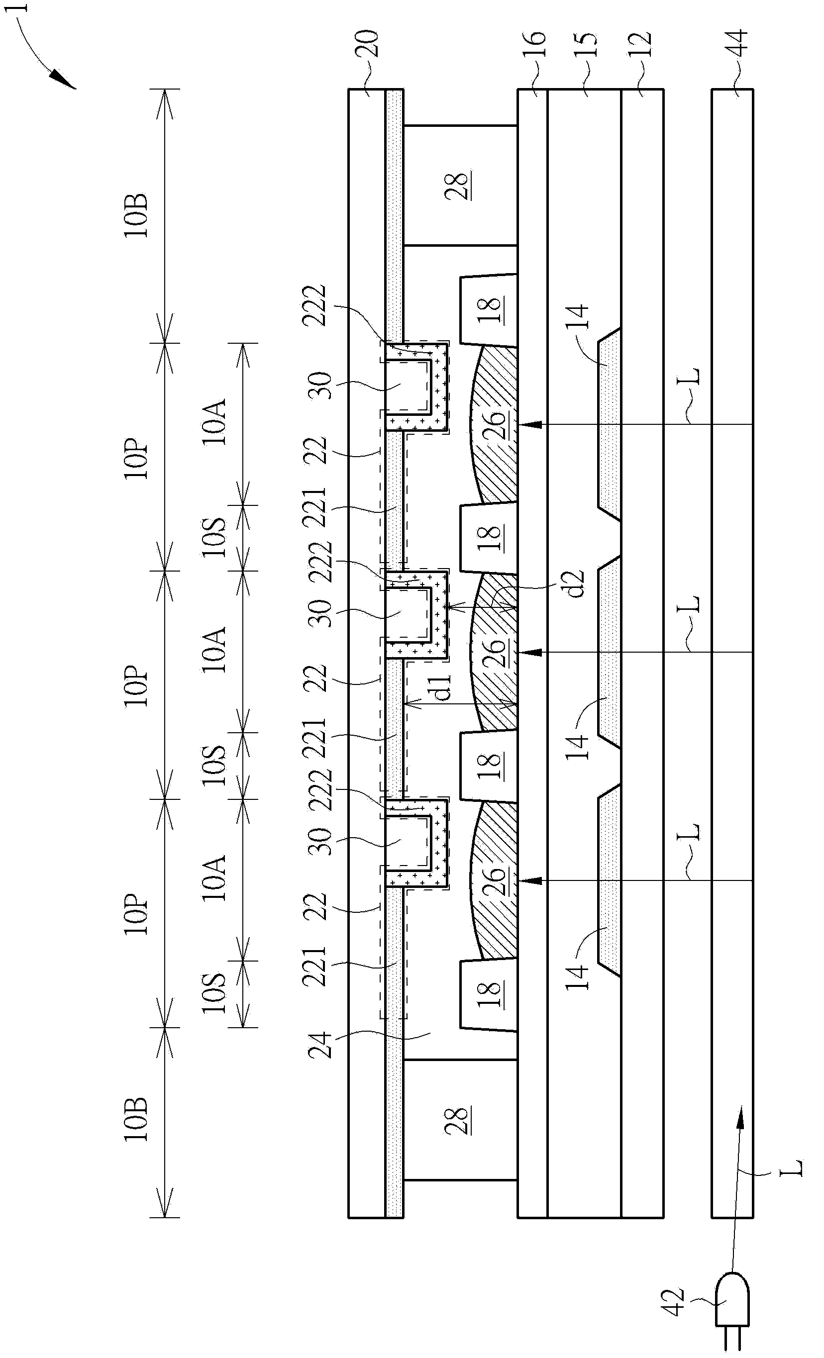
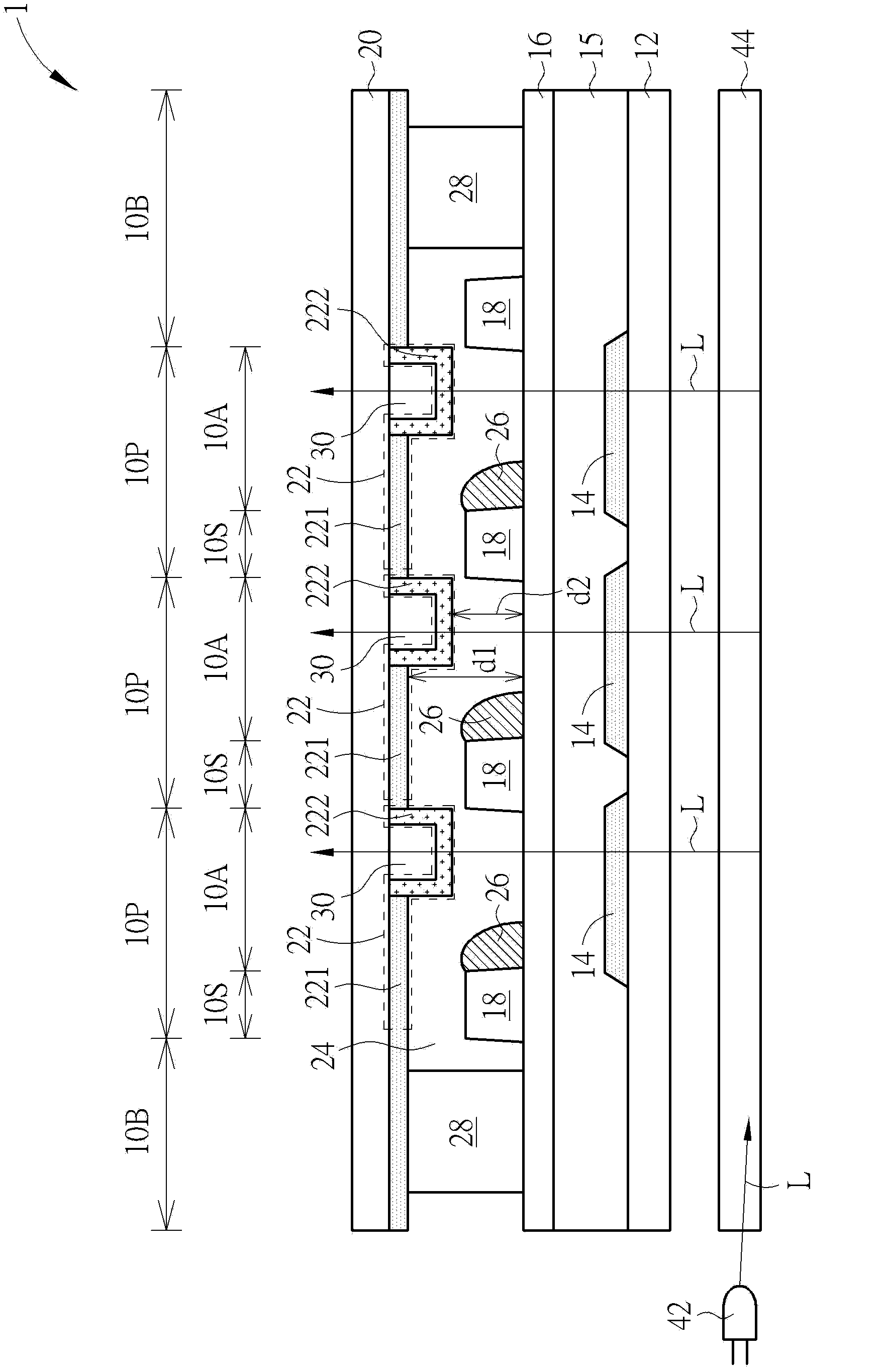
[0059] Please refer to figure 1 and figure 2 . figure 1 and figure 2 A schematic diagram showing the electrowetting display device of the first embodiment of the present invention, wherein figure 1 It is a schematic diagram of the electrowetting display device in the first embodiment in the dark display mode, figure 2 It is a schematic diagram of the electrowetting display device of the first embodiment in the bright state display mode. Such as figure 1 and figure 2As shown, the electrowetting display device 1 of this embodiment has a plurality of pixel regions 10P, and each pixel region 10P includes an active region 10A an...


PUM


Abstract

The invention discloses an electrowetting display device. The electrowetting display device comprises a plurality of pixel areas, and each pixel area includes a pixel perimeter area and an active area. The electrowetting display device also comprises a first substrate, a plurality of first electrodes, a hydrophobic layer, a plurality of barrier walls, a second substrate, a plurality of second electrodes, a polar liquid and a non polar liquid. The first electrode is positioned on the first substrate. Each second electrode includes a first sub electrode part and a second sub electrode part which are arranged in the corresponding active area and mutually and electrically connected, a first distance is present between the first sub electrode part and the hydrophobic layer, a second distance is present between the second sub electrode part and the hydrophobic layer, and the first distance is larger than the second distance. The polar liquid and the non polar liquid are arranged between the second electrode and the hydrophobic layer.

Description

technical field [0001] The invention relates to an electrowetting display device, especially an electrowetting display device with multiple gaps. Background technique [0002] An electrowetting display device is a display device that uses electrowetting force to control the movement of non-polar liquid and polar liquid to achieve display effect. The electrowetting display device mainly includes two substrates, two electrodes respectively placed inside the two substrates, and a non-polar liquid and a polar liquid which are arranged between the two electrodes and are immiscible with each other. The voltage difference applied between the two electrodes can change the hydrophilic effect of the electrodes, thereby changing the contact angle. That is to say, in the absence of voltage difference, the electrode surface is more hydrophobic and oleophilic, and after the voltage difference is applied, the electrode surface will become more hydrophilic and oleophobic, so the area cover...

Claims


Application Information

Patent Timeline
Patent Type & Authority Applications(China)
IPC IPC(8): G02B26/02
Inventor 林炫佑林依萦黄泰翔
Owner AU OPTRONICS CORP
Why Eureka
Try Eureka