Magnetic head installing method and structure based on same

An installation method and magnetic head technology, applied in the configuration/installation of recording head, magnetic recording, instruments, etc., can solve the problems of thick card scratcher, inconvenient disassembly and assembly of the magnetic head, etc., and achieve reduced thickness, convenient disassembly and assembly, and structural simple effect

Active Publication Date: 2013-12-11
FUJIAN LANDI COMML EQUIP CO LTD
View PDF8 Cites 3 Cited by
  • Summary
  • Abstract
  • Description
  • Claims
  • Application Information

AI Technical Summary

Problems solved by technology

[0003] The purpose of the present invention is to provide a magnetic head installation method and its structure, which helps to solve the problems of the existing card scribes, such as thicker thickness and inconvenient disassembly and assembly of the magnetic head, etc.

Method used


Image

  • Magnetic head installing method and structure based on same
  • Magnetic head installing method and structure based on same
  • Magnetic head installing method and structure based on same

Examples


Embodiment Construction

[0024] In order to make the above-mentioned features and advantages of the present invention more comprehensible, the following specific embodiments are described in detail with reference to the accompanying drawings.

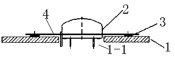
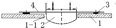
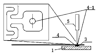
[0025] refer to figure 1 , figure 2 , image 3 and Figure 4 , the present invention relates to a kind of magnetic head installation method, carry out as follows:

[0026] 1) A metal shrapnel is preset on the magnetic head to ensure that the magnetic head can move back and forth in the vertical direction;

[0027] 2) A magnetic head window for accommodating the magnetic head is provided on the PCB;

[0028] 3) Solder the two positioning pieces on both sides of the magnetic head window of the PCB board respectively through the surface mount process;

[0029] 4) Weld one end of the metal shrapnel to a positioning piece;

[0030] 5) Weld the other end of the metal shrapnel to the other positioning piece.

[0031] In step 1, the metal shrapnel and the magne...


PUM


Abstract

The invention relates to a magnetic head installing method. The magnetic head installing method is characterized by comprising the following steps: 1) a metal spring sheet is prearranged on a magnetic head and is used for ensuring the front-and-back movement of the magnetic head in vertical direction; 2) a magnetic head window for accommodating the magnetic head is formed on a PCB (Printed Circuit Board); 3) two locating pieces are respectively welded on two sides of the magnetic head window of the PCB by adopting a surface mounting technology; 4) one end of the metal spring sheet is welded on one locating piece; 5) the other end of the metal spring sheet is welded on the other locating piece. The magnetic head installing method is simple in structure and convenient and fast to install and remove, nickel pieces are firstly surface-mounted on the PCB, then the magnetic head with the spring sheet is welded on the nickel pieces through adopting an electrowelding technology, so that not only can the thickness of a card swiper be reduced, but also the replacement and maintenance of the faulted magnetic head can be guaranteed.

Description

technical field [0001] The invention relates to the field of electronic payment, in particular to a magnetic head installation method and its structure. Background technique [0002] The previous design of the card scribe requires screws and pressure blocks to fix the magnetic head on the structural parts. The length of the screw increases the thickness of the card scribe, resulting in a larger structure, and also brings great difficulties to the disassembly and assembly of the magnetic head replacement. inconvenient. Therefore, it is the object of the present invention to study the above problems. Contents of the invention [0003] The object of the present invention is to provide a magnetic head installation method and its structure, which help to solve the problems of the existing card scribes, such as thicker thickness and inconvenient assembly and disassembly of the magnetic head. [0004] One of the technical solutions of the present invention is: a method for inst...

Claims


Application Information

Patent Timeline
Patent Type & Authority Applications(China)
IPC IPC(8): G07F9/00G07G1/12
CPCG11B5/00808G11B5/48
Inventor 林魁
Owner FUJIAN LANDI COMML EQUIP CO LTD
Why Eureka
Try Eureka