
High-pressure controllable slide valve type mechanical combination sealing system

A combined sealing and slide valve technology, which is applied in the direction of engine sealing, mechanical equipment, engine components, etc., can solve the problem of high-pressure reliable sealing and sealing components that cannot meet the requirements of dangerous chemical media, online disassembly and replacement of sealing components under pressure, maintenance of sealing components Problems such as poor operability and reduced dynamic stability of the rotating spindle achieve the effects of reducing and avoiding leakage and major accidents, convenient and quick disassembly and replacement, and improving maintenance time

Inactive Publication Date: 2010-09-08
ZHEJIANG UNIV
View PDF0 Cites 1 Cited by
  • Summary
  • Abstract
  • Description
  • Claims
  • Application Information

AI Technical Summary

Problems solved by technology

This type of sealing structure is also relatively simple and does not require external human intervention. However, the existence of the centrifuge often reduces the dynamic stability of the rotating spindle, so it is not suitable for use at high speeds, and the sealing pressure in the parking state is not high.
[0007] To sum up, most of the combined sealing products commonly used at present have low parking sealing pressure, poor sealing reliability, and poor operability for maintenance of sealing components, and none of them can meet the high-pressure reliable sealing of hazardous chemical media and the online pressure of sealing components. Disassembly and replacement

Method used


Image

  • High-pressure controllable slide valve type mechanical combination sealing system
  • High-pressure controllable slide valve type mechanical combination sealing system

Examples


Embodiment Construction

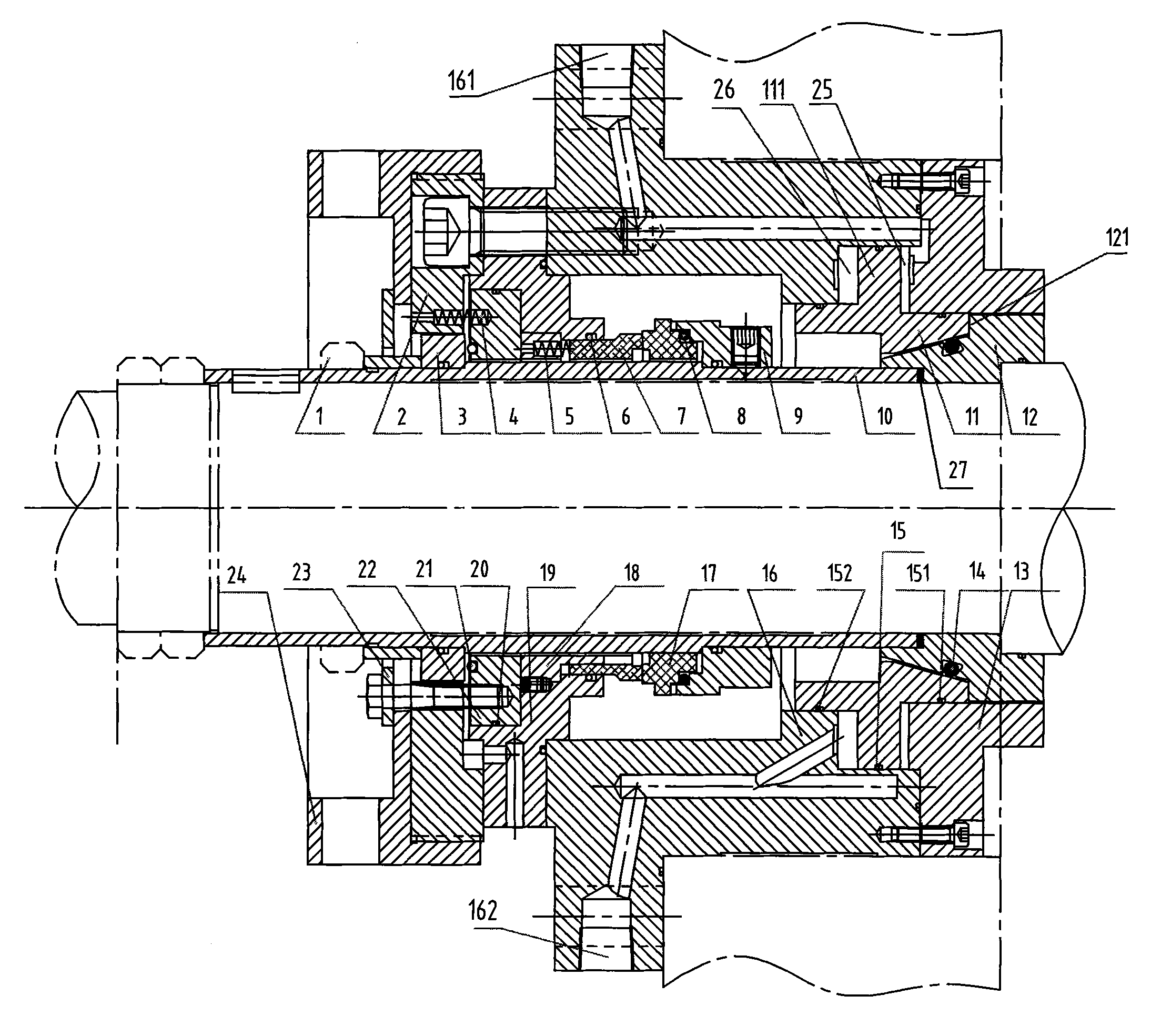
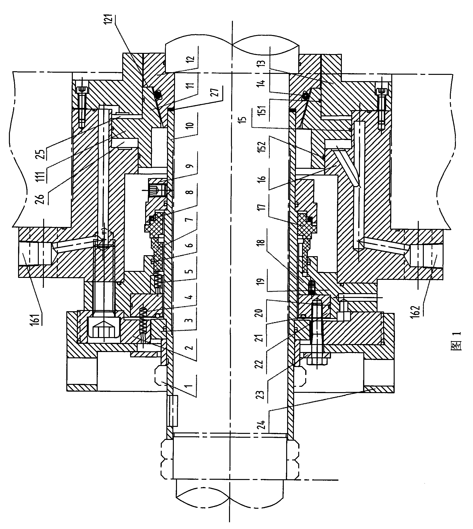
[0028] Figure 1 shows a high-pressure controllable spool valve mechanical combined sealing system, which consists of the following three parts arranged from right to left: controllable spool valve static seal assembly, rotating mechanical seal assembly and emergency seal assembly.

[0029] The static seal assembly of the controllable spool valve includes a tapered bushing 12 for fitting on the shaft shoulder. The tapered bushing 12 is located in the spool valve gland 13. The tapered bushing 12 consists of a hollow cylindrical section and a hollow cone The outer surface of the hollow cylindrical section and the inner surface of the slide valve gland 13 form a certain gap, the gap is generally 0.5 ~ 1mm; the outer surface of the hollow conical section of the tapered sleeve 12 is provided with a dovetail groove, The main sealing ring 14 is placed in the dovetail groove, and the main sealing ring 14 can be an O-shaped rubber ring.

[0030] The inner surface of the spool valve 11 f...


PUM


Abstract

The invention discloses a high-pressure controllable slide-valve type mechanical combined sealing system. The system comprises a controllable slide valve stationary seal assembly and a rotating mechanical seal assembly; the controllable slide valve stationary seal assemble comprises a slide valve gland (13), a slide valve (11) and a tapered shaft sleeve (12) sheathed on a shaft shoulder, the tapered shaft sleeve (12) is positioned inside the slide valve gland (13), the slide valve (11) which is partially positioned in a flange (16) is hermetically connected with the tapered shaft sleeve (12) in a sliding way, and the flange (16) is provided with a pressure source channel I (161) and a pressure source channel II (162) which are respectively used for controlling the slide valve (11) to slide leftwards or slide rightwards; the rotating mechanical seal assembly comprises a rotating seat (9) which is fixedly connected with a shaft sleeve (10), a rotating ring (17) and a stationary ring (7)which are closely jointed on a seal face and the like. The sealing system can help greatly reduce and avoid leakage of dangerous fluid and serious accidents.

Description

technical field [0001] The invention relates to a combined rotary shaft seal, more specifically a combined rotary shaft seal composed of a multi-stage sealing structure, which belongs to the technical field of sealing. Background technique [0002] The combined sealing system is widely used in fluid machinery and other transmission power equipment to meet the needs of sealing and maintenance in different operating conditions. At present, the traditional combined seals that are widely used mainly include packing-mechanical seals, mechanical seals- Inflatable seal, auxiliary impeller-slide valve seal, mechanical seal-centrifugal parking seal, etc. [0003] The packing-mechanical seal combined seal is a combined seal used in combination with a packing seal and a rotary combined seal. The packing seal can be used as a backup rotary seal of the mechanical seal and an emergency seal in the parking state, and can realize high-pressure sealing. However, its overall axial length is ...

Claims


Application Information

Patent Timeline
Patent Type & Authority Patents(China)
IPC IPC(8): F16J15/16
Inventor 王乐勤孟祥铠戴维平吴大转郑水英焦磊
Owner ZHEJIANG UNIV
Learn More