Series resonance inverter and implementation method thereof

A series resonance and realization method technology, applied in the electronic field, can solve problems such as unsatisfactory effect and increase the difficulty of heat dissipation structure design, so as to achieve the effect of balanced loss

Active Publication Date: 2013-12-11
NEUSOFT MEDICAL SYST CO LTD
View PDF4 Cites 34 Cited by
  • Summary
  • Abstract
  • Description
  • Claims
  • Application Information

AI Technical Summary

Problems solved by technology

Its switch adopts phase-shift PWM control. Since this phase-shift control is an asymmetrical control method, its advanced forearm and lagging arm are switched in turn, and each switching device will have a zero-voltage turn-on and a zero-voltage switch-on every two switching cycles. turn off, and its switching frequency remains unchanged, which will inevitably cause different degrees of switching loss to the switching device, which makes the design of the heat dissipation structure more difficult.
[0004] In order to achieve the balanced loss of the switch, the principle that the RCD Snubber circuit on...

Method used


Image

  • Series resonance inverter and implementation method thereof
  • Series resonance inverter and implementation method thereof
  • Series resonance inverter and implementation method thereof

Examples


Embodiment Construction

[0023] Specific embodiments of the present invention will be described in detail below in conjunction with the accompanying drawings.

[0024] In view of the aforementioned existing series resonant inverter circuit, in realizing the switching loss and heat dissipation structure design, due to the different losses of the switching devices, it is difficult to increase the difficulty of the heat dissipation structure design. , to achieve balanced loss of the switch, which is beneficial to the design of the heat dissipation structure.

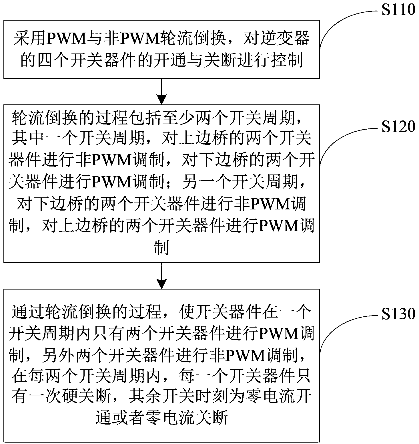
[0025] In order to describe in detail the implementation method of the series resonant inverter provided by the present invention, figure 1 A schematic flowchart of a method for implementing a series resonant inverter according to an embodiment of the present invention is shown.

[0026] Such as figure 1 As shown, the implementation method of the series resonant inverter provided by the present invention includes:

[0027] S110: Control the turn...


PUM


Abstract

The invention provides a series resonance inverter and an implementation method of the series resonance inverter. The implementation method of the series resonance inverter comprises the steps that control over starting and stopping of four switching devices of the series resonance inverter is carried out through alternate switching between PWM modulation and non-PWM modulation, wherein the starting frequency and the stopping frequency of the switching devices are adjusted according to resonance current. The process of alternate switching comprises at least two switching periods, wherein in one of the switching periods, two paths of driving signals are used for driving two switching devices of an upper edge bridge to carry out non-PWM modulation so that the two switching devices can work with a preset duty ratio, the other two paths of driving signals are used for driving two switching devices of a lower edge bridge to carry out PWM modulation; in the other switching period, the two paths of driving signals are used for driving the two switching devices of the lower edge bridge to carry out non-PWM modulation so that the two switching devices can work with the preset duty ratio, and the other two paths of driving signals are used for driving the two switching devices of the upper edge bridge to carry out PWM modulation. The series resonance inverter and the implementation method of the series resonance inverter can be beneficial to achieving loss balance of the switching devices and the design of heat dissipation structures of the switching devices.

Description

technical field [0001] The present invention relates to the field of electronic technology, and more specifically, to a series resonant inverter and an implementation method thereof. Background technique [0002] Nowadays, in the high-voltage power supply of X-ray machines, the series resonant inverter circuit is the commonly used topology. In the series resonant circuit, the design of the switch loss and heat dissipation structure is the core of the series resonant circuit. Therefore, how to reduce the switching loss and optimize the design of the heat dissipation structure has always been the main problem faced by the series resonant circuit. [0003] In the existing high-voltage power supply, a full-bridge series resonant circuit, phase-shift control, and alternate switching between the leading arm and the lagging arm are used to solve the problem of equalizing loss of the switch. Its switch adopts phase-shift PWM control. Since this phase-shift control is an asymmetrica...

Claims


Application Information

Patent Timeline
IPC IPC(8): H02M7/48
Inventor 崔宇航高红宇韩吉龙
Owner NEUSOFT MEDICAL SYST CO LTD
Why Eureka
Try Eureka