Pilot frequency space variable carrier frequency offset estimation method

A technology of pilot spacing and carrier frequency offset, applied to baseband system components, etc., can solve the problems of complex framing, increasing the number of pilots, and small frequency offset estimation range, achieving high estimation accuracy, expanding estimation range, The effect of optimizing the design

Inactive Publication Date: 2013-12-11
XIDIAN UNIV
View PDF5 Cites 5 Cited by
  • Summary
  • Abstract
  • Description
  • Claims
  • Application Information

AI Technical Summary

Problems solved by technology

Although these two pilot structures expand the range of frequency estimation to a certain extent, when the data is very long or the frequency offset is large, even these two pilot structures cannot meet the required estimation range, so they can only be discarded. Or increase the number of pilots
On the other hand, since the two pilot structures need to divide the pilot and data into many segments for insertion and insertion, the framing is more complicated
[0005] To sum up, the PP structure is to divide the pilot into two segments and put them at the beginning and end of the data, while other existing pilot structures such as PMP structure, PMMP structure, L-PP structure, etc. are based on the PP structure. In the above, the data and pilot are divided into several segments on average for insertion and insertion; the characteristics of these existing pilot structures are similar to those of the PP structure, and there is a disadvantage that the frequency offset estimation range is small, and the longer the data length, the wider the estimation range. Small

Method used


Image

  • Pilot frequency space variable carrier frequency offset estimation method
  • Pilot frequency space variable carrier frequency offset estimation method
  • Pilot frequency space variable carrier frequency offset estimation method

Examples


Embodiment Construction

[0040] The embodiments of the present invention will be further described below in conjunction with the accompanying drawings.

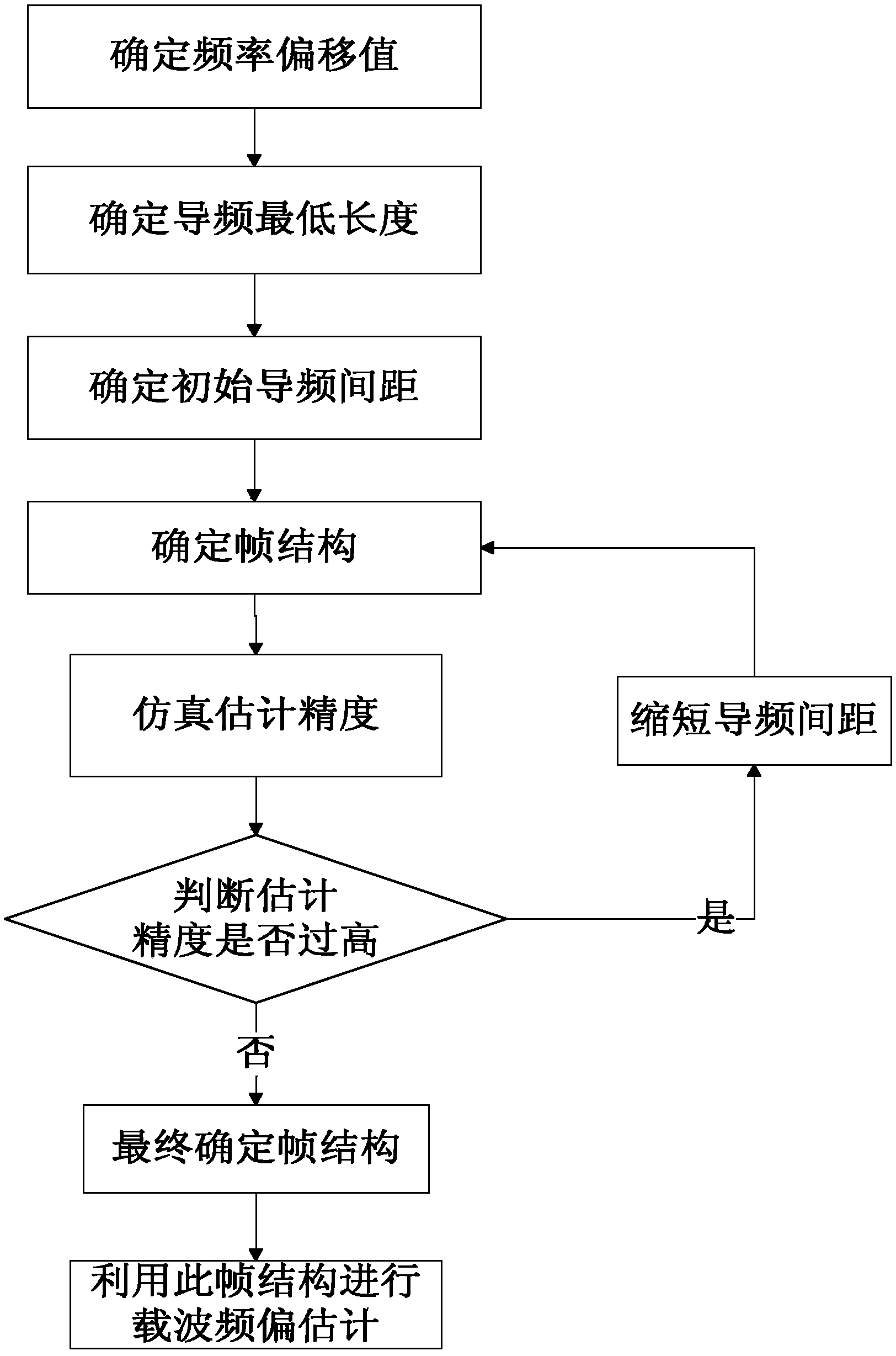
[0041] refer to figure 1 , the implementation steps of the present invention are as follows:

[0042] Step 1: According to the impact of different frequency offsets on the data with a length of N symbols, determine the normalized frequency offset value R=ΔfT under the condition of 0.5dB SNR loss s , where Δf refers to the frequency offset value, T s Refers to the symbol period:

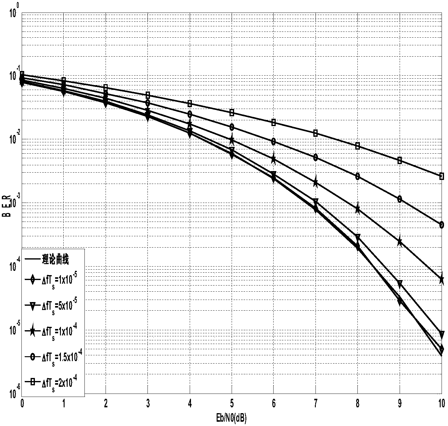
[0043] (1a) carry out QPSK modulation to the binary data Y that length is N symbol, obtain the signal H after modulation;

[0044](1b) Add frequency offset values ​​of different sizes to the modulated signal H, and add noise to obtain the signal H1 after adding frequency offset and noise;

[0045] (1c) performing QPSK demodulation on the signal H1 after adding frequency offset and noise to obtain demodulated signal H2;

[0046] (1d) Compare the demodulated signal H2 wit...


PUM


Abstract

The invention discloses a pilot frequency space variable carrier frequency offset estimation method, which mainly solves the problems of small frequency offset estimation range and reduction in estimation range with increase in data length existing in the prior art. The method comprises the following implementation steps: (1) determining a normalized frequency offset value R in case that a 0.5dB signal-noise ratio loss condition is met according to the influence of different frequency offsets on data with length of N symbols; (2) determining the minimum pilot frequency length L according to the normalized frequency offset value R; (3) determining an initial space D according to the minimum normalized estimation value J required by the system; (4) determining an initial frame structure according to the initial space; (5) simulating the estimation accuracy and judging by using the initial frame structure and finally determining the pilot frequency space; (6) determining a final frame structure by using the finally determined pilot frequency space; (7) performing carrier frequency offset estimation by using the determined final frame structure. The normalized estimation range can reach -2.25*10<-3> to 2.25*10<-3> under the condition that the estimation accuracy is 5*10<-5>; the method can be used for carrier synchronization and wireless channel estimation of a wireless communication system.

Description

technical field [0001] The present invention belongs to the technical field of wireless communication, and further relates to a method for estimating carrier frequency offset with variable pilot spacing in the technical field of signal detection and estimation. The present invention can be used in carrier frequency offset estimation of a wireless communication system. The spacing ensures the effectiveness of carrier frequency offset estimation, thereby ensuring that communication can be effectively performed within a larger frequency offset range. Background technique [0002] Carrier frequency offset has a serious impact on communication systems such as modulation, coding, and spread spectrum. Especially in the case of many constellation points, even a small frequency offset may cause constellation point offset and lead to misjudgment of information. Therefore, Accurate carrier frequency estimation and compensation are required before detection, decoding and despreading. I...

Claims


Application Information

Patent Timeline
Patent Type & Authority Applications(China)
IPC IPC(8): H04L25/02
Inventor 孙锦华丁玉杰王雪梅韩会梅刘鹏
Owner XIDIAN UNIV
Why Eureka
Try Eureka