Cutting insert and indexable rotary cutting tool

A technology of cutting inserts and cutting tools, applied in milling cutting inserts, manufacturing tools, milling cutters, etc., can solve the problems of rigidity reduction of the main body of the tool, and achieve the effects of excellent surface roughness, reliable fixation and maintenance, and reduced damage

Inactive Publication Date: 2013-12-11
TUNGALOY CORP
View PDF8 Cites 0 Cited by
  • Summary
  • Abstract
  • Description
  • Claims
  • Application Information

AI Technical Summary

Problems solved by technology

In order to facilitate threading, the chip flute must be enlarged more than necessary, and in this case, the rigidity reduction of the tool body becomes a problem

Method used


Image

  • Cutting insert and indexable rotary cutting tool
  • Cutting insert and indexable rotary cutting tool
  • Cutting insert and indexable rotary cutting tool

Examples


no. 1 Embodiment approach

[0079] As shown in FIG. 1, the cutting insert 1 according to the first embodiment defines an upper surface 2 and a lower surface 3 having a polygonal shape; a plurality of side surfaces 4, 5, 6 extending between these upper surfaces 2 and lower surfaces 3 , 7, 8; and a mounting hole 9 running through the upper surface 2 and the lower surface 3. The upper surface 2 and the lower surface 3 have the same shape and are opposed to each other approximately in parallel.

[0080] upper surface 2 as Figure 1A As shown, it has a left-right symmetrical shape in a top view. In addition, the lower surface 3 also has a left-right symmetrical shape. Here, five intersecting portions 10 , 11 , 12 , 13 , and 14 intersecting the five side surfaces 4 , 5 , 6 , 7 , and 8 exist on the upper surface 2 . exist Figure 1A Among these intersections, the upper left one is the first intersection 10 ; In addition, the third intersection 14 is located adjacent to the first intersection 10 on the lowe...

no. 2 Embodiment approach

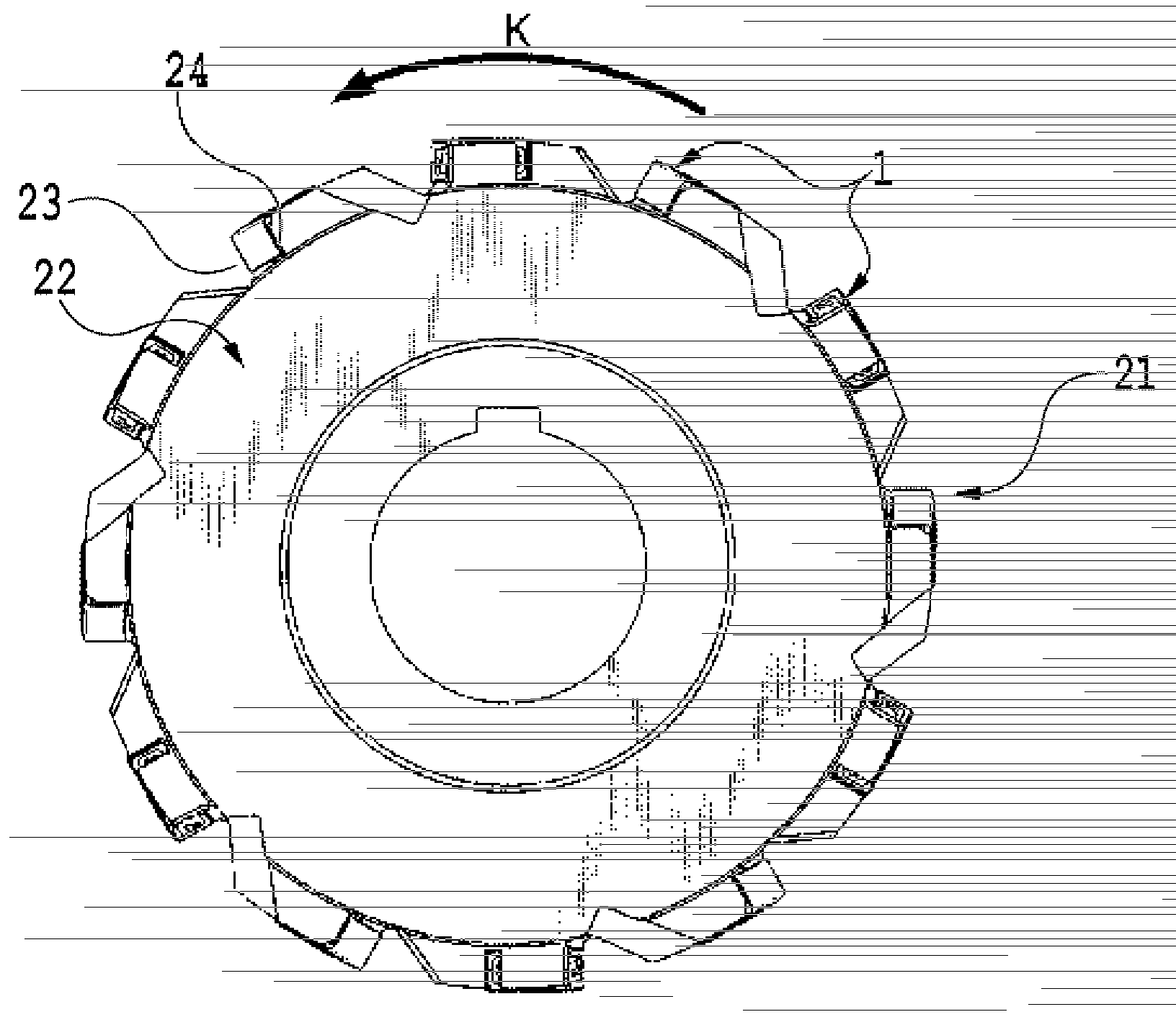
[0093] Next, refer to image 3 A second embodiment of the present invention will be described. In the cutting insert 31 of the present embodiment, the description of the same configuration as that of the cutting insert 1 of the first embodiment is omitted.

[0094] Such as image 3 As shown, in this embodiment, in addition to the first intersecting portion 10 and the second intersecting portion 11 on the upper and lower surfaces, the fifth intersecting portion 13 on the upper surface 2 and the lower surface 3 is used as a cutting edge, respectively. Thus, the cutting edges in this embodiment are 2 cutting edges for the left side, 2 cutting edges for the right side, and 2 cutting edges in the center, a total of 6 cutting edges. Honing may also be performed on the fifth intersecting portion 13 as a cutting edge. A rake face 7a is formed on the side surface 7 in contact with the fifth intersection portion 13 of the upper and lower surfaces. The rake face 7 a is formed by grad...

no. 3 Embodiment approach

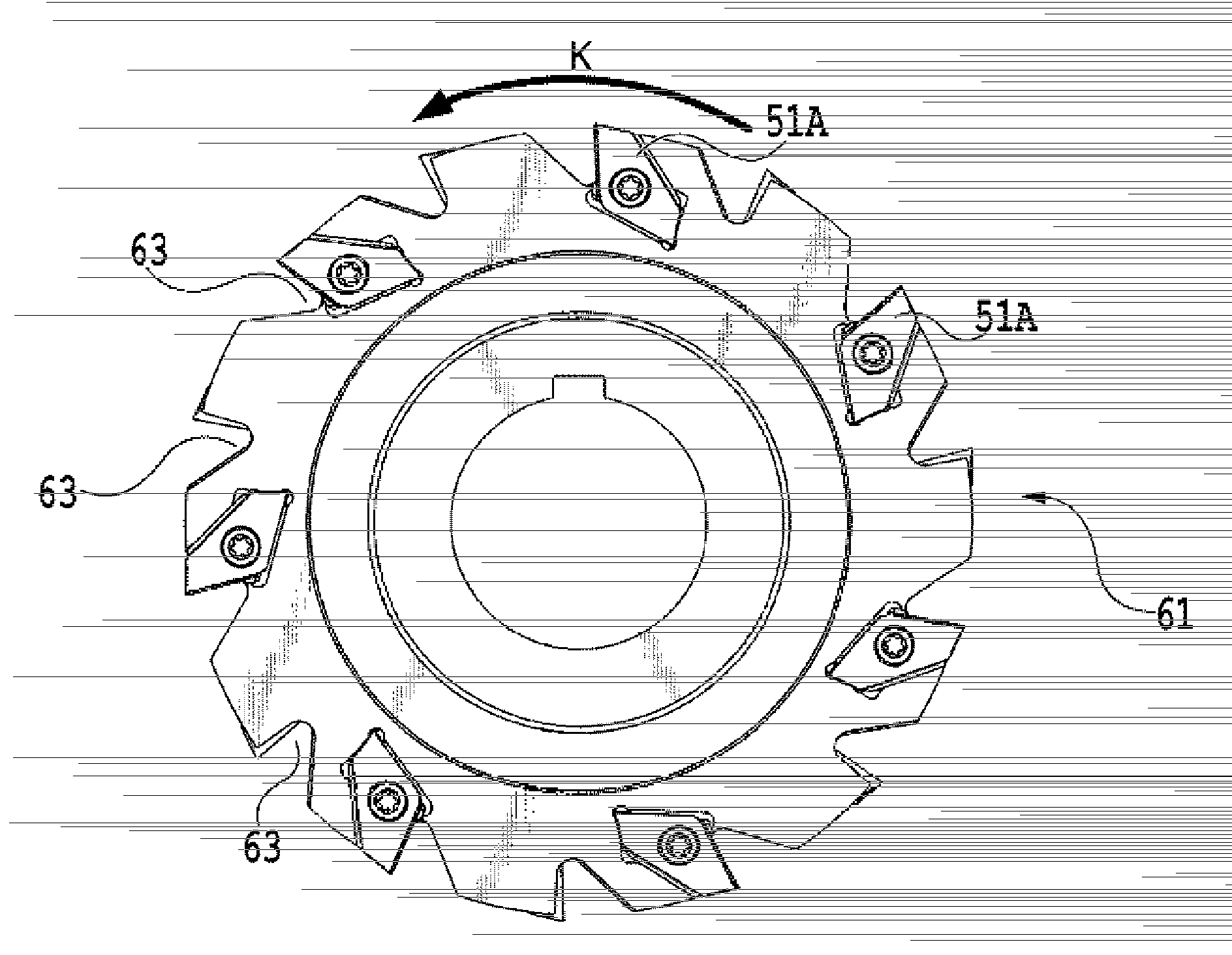
[0102] Next, refer to Figure 5 The cutting insert 51 of the third embodiment will be described. In the cutting insert of the present embodiment, the description of the same configuration as that of the cutting insert of the first embodiment is omitted.

[0103] Such as Figure 5 As shown, in this embodiment, the side intersection portion 52 between the side surface 4 and the side surface 8 and the side intersection portion 53 between the side surface 5 and the side surface 6 are used as cutting edges. No cutting edge is formed other than these side intersections 52 and 53 . Rake faces 4b, 5b are formed on the side surfaces 4, 5 . The rake faces 4b, 5b are formed to gradually incline toward the inside of the cutting insert 51 from the side intersection portion. On the side faces 4 and 5 where the rake faces 4b and 5b are formed, the bottom may be formed by a flat surface, may also be formed by a curved surface, or may be formed by a plurality of intersecting inclined surfa...


PUM


Abstract

Provided is a cutting insert that has reduced area when viewed from above and is disposed so as to lie tangent to the outer periphery of a tool body. The top surface (2) has five or more intersection parts (10, 11, 12, 13, 14) where the top surface intersects with a plurality of side surfaces (4, 5, 6, 7, 8). The five or more intersection parts include first and second intersection parts (10, 11), and third and fourth intersection parts (14, 12) that are shorter than the first and second intersection parts (10, 11) respectively. Cutting edges are formed on the first and second intersection parts (10, 11). Rake faces (4a, 5a) are formed on the side surfaces (4, 5) corresponding to the first and second intersection parts (10, 11) respectively. A flank face for forming the cutting edges is formed on the top surface (2).

Description

technical field [0001] The present invention relates to a cutting insert and an indexable rotary cutting tool equipped with the cutting insert. More specifically, the present invention relates to a cutting insert used for grooving and an indexable rotary cutting tool for grooving. Background technique [0002] An indexable side cutter is known as one of rotary cutting tools capable of grooving. There are the following types of plate-shaped cutting inserts mounted on the indexable side cutter: the type that uses either of the upper and lower surfaces as the rake face, and is arranged radially on the outer peripheral surface of the disc-shaped tool body; The side face is used as the rake face, and is arranged along the tangential direction of the circumference on the outer peripheral surface of the disc-shaped tool body. The type arranged along the radial direction is also called a flat type. The type arranged along the tangential direction is also called vertical type. ...

Claims


Application Information

Patent Timeline
Patent Type & Authority Applications(China)
IPC IPC(8): B23C5/20B23C5/08
CPCB23C5/08B23C2200/0416B23C2200/0444B23C2200/367B23C2210/66B23C5/2213Y10T407/235Y10T407/23Y10T407/1942B23C5/202B23C5/205
Inventor K.S.布哈加斯
Owner TUNGALOY CORP
Why Eureka
Try Eureka