Helical gear heading mold

A helical gear and upsetting technology, which is applied in the manufacture of tools, wheels, forging/pressing/hammering machinery, etc., can solve the problems of high manufacturing cost of helical gears, long processing cycle of helical gears, low processing efficiency, etc.

Active Publication Date: 2015-06-10
宁波振华汽车零部件有限公司
View PDF9 Cites 1 Cited by
  • Summary
  • Abstract
  • Description
  • Claims
  • Application Information

AI Technical Summary

Problems solved by technology

[0002] Small-sized helical gears are widely used in many industries, especially in the automotive industry. At present, the production methods of helical gears are nothing more than machining or die-casting. The processing efficiency of helical gears is low, and the processing cycle of helical gears is long. Gear manufacturing costs are high

Method used


Image

  • Helical gear heading mold
  • Helical gear heading mold

Examples


Embodiment Construction

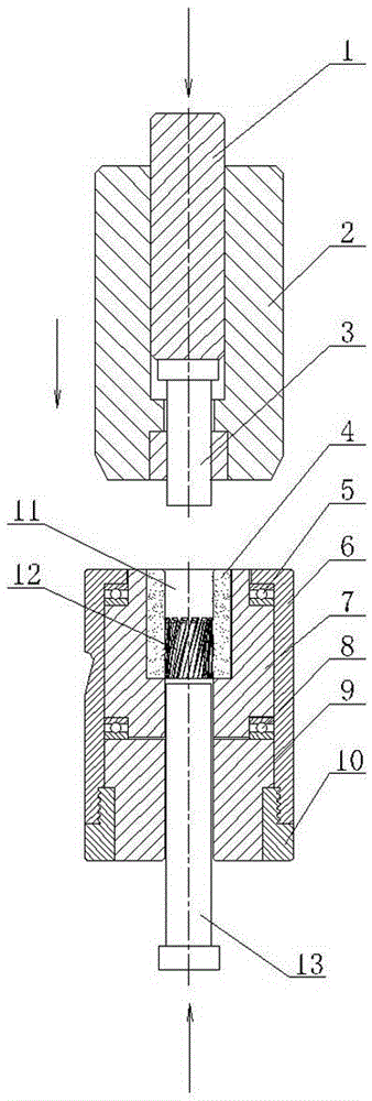
[0010] Such as figure 1 As shown, the helical gear upsetting mold of the present invention is composed of an upper die and a lower die, and the upper die includes an upper die cover 2 and a punch 3, and the punch 3 is movable up and down in the inner hole of the upper die cover 2, punching The top of the head 3 is provided with a push rod 1; the lower mold includes a lower mold cover and a rotary mold body 7, the lower mold cover is screwed by an upper sleeve 6 and a lower sleeve 10, and the rotary mold body 7 passes through the upper The plane bearing 5 and the lower plane bearing 8 are rotatably arranged in the inner cavity of the lower mold sleeve, the upper end surface of the upper plane bearing 5 is supported on the end surface of the inner hole of the upper sleeve 6, and the lower end surface of the lower plane bearing 8 is supported on the pad mold 9, The cushion mold 9 is fixed in the upper mold sleeve when the upper and lower sleeves are screwed tightly, and the middl...


PUM


Abstract

The invention discloses a helical gear heading mold. The helical gear heading mold consists of an upper die and a lower die, and is characterized in that the upper die comprises an upper die sleeve and a punch, wherein the punch is arranged in an inner hole of the upper die sleeve in a vertically moving manner; the lower die comprises a lower die sleeve and a rotary die body; the rotary die body is rotatably arranged in a cavity of the lower die sleeve through upper and lower planar bearings; an inner hole is formed in the middle of the rotary die body for fixing an alloy die core; the alloy die core is provided with a helical gear heading die cavity; the upper section of the die cavity is provided with a straight hole; the lower section of the die cavity is provided with a helical gear cavity which has the same shape as that of a headed helical gear; the bottom of the die cavity is communicated with a rear through ejector rod guide hole; a rear through ejector rod is movably arranged in the rear through ejector rod guide hole; during cold heading forming of the helical gear, the bottom surface of the upper die sleeve is tightly attached to the top surface of the alloy die core, and the head of the punch extends into the die cavity of the alloy die core. According to the helical gear heading mold, cold heading forming of helical gears on cold heading equipment can be realized, the helical gear machining efficiency is greatly improved, the helical gear machining period is shortened and the helical gear manufacturing cost is reduced.

Description

technical field [0001] The invention relates to a cold heading die, in particular to a helical gear heading die. Background technique [0002] In many industries, especially in the automotive industry, small-sized helical gears are widely used. At present, the production methods of helical gears are nothing more than machining or die-casting. The processing efficiency of helical gears is low, and the processing cycle of helical gears is long. Gears are expensive to manufacture. Contents of the invention [0003] Aiming at the deficiencies in the prior art, the object of the present invention is to provide a helical gear upsetting die which can realize the cold upsetting processing of helical gears on cold upsetting equipment. [0004] The present invention is implemented through the following technical solutions: [0005] The helical gear upsetting die is composed of an upper die and a lower die, and is characterized in that: the upper die includes an upper die sleeve an...

Claims


Application Information

Patent Timeline
Patent Type & Authority Patents(China)
IPC IPC(8): B21J13/02B21K1/30
Inventor 陈雄武
Owner 宁波振华汽车零部件有限公司
Why Eureka
Try Eureka