Magnet forming die

A technology for forming molds and magnets, which is applied in the field of molds, can solve the problems of low orientation of magnets and large magnetic declination angles of magnets, and achieve the effects of improving orientation, reducing magnetic declination angles, and reducing deflection angles

Inactive Publication Date: 2013-12-18
NINGBO YUNSHENG +5
View PDF7 Cites 5 Cited by
  • Summary
  • Abstract
  • Description
  • Claims
  • Application Information

AI Technical Summary

Problems solved by technology

The above situation causes the magnetic powder at both ends of the product to deflect with the magnetic field lines, and the schematic diagram of the magnetic circuit distribution is as follows image 3 As shown, the magnetic declination angle of the magnet is too large, and the orientation of the magnet is not high.

Method used


Image

  • Magnet forming die
  • Magnet forming die
  • Magnet forming die

Examples


Embodiment 1

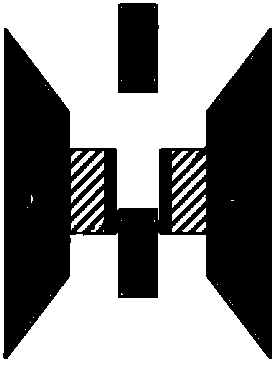
[0027] Example 1: In this example, it is necessary to prepare a sintered NdFeB square magnet. According to the design requirements of the sintered NdFeB square magnet, the size of the magnet compact is required to be 38.5mm×34mm×24.5mm, and 34mm represents the magnetic orientation direction of the magnet compact 38.5mm is the width of the magnet compact, 24.5mm is the thickness of the magnet compact in the pressing direction, and the loose magnetic powder density is 2.0g / cm 3 , the magnet compact density is 4.0g / cm 3 , we choose the size of the mold cavity to be 38.5mm×34mm×100mm, the demoulding angle is 1°, the cross-sectional dimensions of the upper punch 2 and the lower punch 3 are both 38.5mm×34mm, and the thickness of the carbide sleeve 12 is 15mm , the distance between the S pole head and the N pole head of the magnetic orientation device 4 is 140mm, and the inner end surface of the soft magnetic material block 15 is the same as the cross-sectional shape of the loose mag...

Embodiment 2

[0029] Example 2: In this example, it is necessary to prepare a sintered NdFeB VCM (voice coil motor) magnet. According to the design requirements of the sintered NdFeB VCM magnet, the cross-sectional shape of the magnet compact is as follows Figure 9 As shown, the size of the magnet compact is required to be 50mm×47.3mm×20.5mm, 50mm represents the length of the magnet compact in the direction of magnetic orientation, 47.3mm represents the width of the magnet compact, and 20.5mm represents the thickness of the magnet compact in the pressing direction. Magnetic powder density is 2.0g / cm 3 , the magnet compact density is 4.0g / cm 3 , we choose the size of the mold cavity to be 50mm×47.3mm×100mm, the demoulding angle is 1°, the cross-sectional dimensions of the upper punch 2 and the lower punch 3 are both 50mm×47.3mm, and the thickness of the carbide sleeve 12 is 10mm , The distance between the S pole head and the N pole head of the magnetic orientation device 4 is 140 mm. Acco...


PUM

PropertyMeasurementUnit
densityaaaaaaaaaa
densityaaaaaaaaaa

Abstract

The invention discloses a magnet forming die which comprises a female die, an upper punch and a lower punch. The female die comprises a die sleeve and a hard alloy sleeve, the die sleeve is made of non-magnetic-permeability materials, the hard alloy sleeve is positioned on the inner side of the die sleeve and is fixedly connected with the die sleeve, a die cavity is formed in the hard alloy sleeve, two symmetrical through holes are formed in side walls of the die sleeve, two soft magnetic material blocks are respectively inlaid in the two through holes, the inner end surfaces of the soft magnetic material blocks are in contact with the hard alloy sleeve, and the shape of the inner end surface of each soft magnetic material block is identical to that of the cross section of loosely filled magnetic powder in the die cavity along the direction of a corresponding magnetic field. The magnet forming die has the advantages that magnetic lines of force of the magnetic fields access the magnetic powder via the two soft magnetic material blocks, and magnetic powder access paths of the magnetic lines of force are guided by the two soft magnetic material blocks, so that magnetic powder entrance deflection angles of the magnetic lines of force are reduced, magnetic declination of a magnet is reduced, and an orientation degree of the magnet is increased.

Description

technical field [0001] The invention relates to a mold, in particular to a magnet forming mold. Background technique [0002] In the magnetic material industry, many magnets (such as: sintered NdFeB, bonded NdFeB, hard ferrite, soft ferrite, magnetic powder core, etc.) are manufactured by powder metallurgy process. For anisotropic magnetic materials such as: sintered NdFeB, bonded NdFeB, barium strontium ferrite and other magnets, which are magnetocrystalline anisotropic magnetic materials, in order to increase the magnetic performance of the magnet, each magnet inside the magnet must be required The degree of crystal orientation should be as consistent as possible, so it is necessary to apply an orientation magnetic field when the compact is formed to keep the orientation of each magnetic powder inside the magnet (hereinafter referred to as magnetic powder) consistent. [0003] Existing magnetic orientation forming presses generally include a magnetic orientation device an...

Claims


Application Information

Patent Timeline
Patent Type & Authority Applications(China)
IPC IPC(8): B22F3/03
Inventor 蔡平平丁勇杨联方毛家福张民
Owner NINGBO YUNSHENG
Why Eureka
Try Eureka