Hydraulic buffer

A technology of hydraulic buffers and oil holes, applied in the field of hydraulic buffers, can solve the problems of non-universal, uneven buffer stop force, uneven deceleration, etc.

Inactive Publication Date: 2013-12-18
KUSN OMNI ELECTRICAL TECH
View PDF6 Cites 14 Cited by
  • Summary
  • Abstract
  • Description
  • Claims
  • Application Information

AI Technical Summary

Problems solved by technology

[0005] The main disadvantages of the hydraulic shock absorber in the prior art are: because only a certain number of orifices are designed in the inner cylinder, but in the actual use process, the amount of oil spilled during throttling is fixed, so it is not universally applicable. Elevators with different rated loads and rated speeds need to be equipped with hydraulic buffers with different oil spillages; in addition, due to the uneven distribution of orifices, there is a problem of uneven buffering and stopping force during the buffering process, that is, there is a problem of buffering and stopping force. The problem of uneven speed

Method used


Image

  • Hydraulic buffer

Examples


Embodiment Construction

[0032] The following will clearly and completely describe the technical solutions in the embodiments of the present invention with reference to the drawings in the embodiments of the present invention.

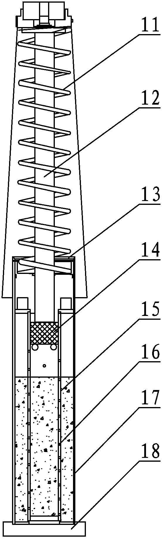
[0033] according to figure 1 , the hydraulic buffer provided by the present invention includes:

[0034] The base, located at the lowest end of the entire hydraulic buffer, is fixed in the pit to support the entire hydraulic buffer;

[0035] The outer cylinder is hollow, and the bottom of the outer cylinder is fixed on the base, which is the outer wall of the hydraulic buffer, and its function is to accept the hydraulic oil flowing out of the inner cylinder;

[0036] The inner cylinder is hollow, and there are oil holes on the cylinder body. The inner cylinder is placed in the hollow chamber inside the outer cylinder, and the bottom of the inner cylinder is fixed on the base. The inner cylinder is a throttling device to control the downstroke of the piston rod. When the spee...


PUM


Abstract

The invention discloses a hydraulic buffer. The hydraulic buffer comprises a base, an outer cylinder, an inner cylinder, a sealing device, a piston, a piston rod and a spring. The inner cylinder is of a hollow type, and the cylinder body of the inner cylinder is provided with oil holes which are evenly distributed in the axial direction of the inner cylinder; the pore sizes of the oil holes are different, and the oil holes are formed in the cylinder body of the inner cylinder at intervals. The hydraulic buffer is of a double-cylinder internal engine oil circulation type, the cylinder body of the inner cylinder is provided with the oil holes of an appropriate number and different pore sizes to generate different oil drain amount according to rated loads and rated speeds of elevators, accordingly needed damping can be generated to achieve the aim of buffering, and the hydraulic buffer can be applicable to elevators of different rated loads and different rated speeds; the oil holes in the inner cylinder are evenly arranged at intervals in the axial direction of the inner cylinder so as to enable the oil pressure of the hydraulic buffer to maintain basically stable and accordingly to enable deceleration of buffering and stopping to be relatively uniform, so that the safety of elevator running can be effectively guaranteed.

Description

technical field [0001] The invention relates to the technical field of buffering, in particular to a hydraulic buffer with good buffering performance. Background technique [0002] The hydraulic buffer used in elevators and other equipment uses hydraulic damping to buffer and decelerate the car or counterweight that is coasting to a stop. That is, when the elevator exceeds the bottom or top floor, the car or counterweight hits the buffer. Buffers absorb or dissipate the elevator's energy, thereby safely slowing the car or counterweight to a stop. Generally, the buffers are installed in the pit, and some buffers are installed on the bottom of the car or the counterweight and run accordingly. Therefore, a support with a height of at least 0.5m must be installed in the pit. For a forced drive elevator, a buffer that can function at the upper limit of the stroke should also be installed on the top of the car. If a counterweight is installed, the buffer installed on the upper p...

Claims


Application Information

Patent Timeline
Patent Type & Authority Applications(China)
IPC IPC(8): B66B5/28F16F9/16
Inventor 高火
Owner KUSN OMNI ELECTRICAL TECH
Why Eureka
Try Eureka