
Valve body structure for manually adjusting fast speed or slow speed of oil pumping

A manual adjustment, speed and slow technology, applied in the direction of fluid pressure actuation device, servo motor assembly, mechanical equipment, etc., to ensure the effect of labor-saving effect

Active Publication Date: 2015-06-17
CHANGSHU TONGRUN AUTO REPAIRING EQUIP
View PDF16 Cites 0 Cited by
  • Summary
  • Abstract
  • Description
  • Claims
  • Application Information

AI Technical Summary

Problems solved by technology

As is well known in the industry, as a jack hydraulic press, labor-saving operation and fast and efficient operation are important design elements. Specifically, when the working cylinder column of the working cylinder is not under force, it can quickly pump the sucked hydraulic pressure with a large amount of oil. The oil is supplied to the working cylinder, and when the working cylinder is under force, it will not cause the operator to work hard, and it can continue to supply oil to the working cylinder of the dive device, so as to ensure the working cylinder column’s ability to process the workpiece (punching, bending, etc.) Processing efficiency, however, there is no technical revelation to meet this requirement in the currently published patent and non-patent literature

Method used

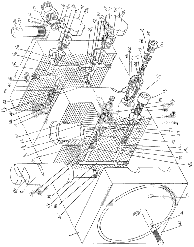
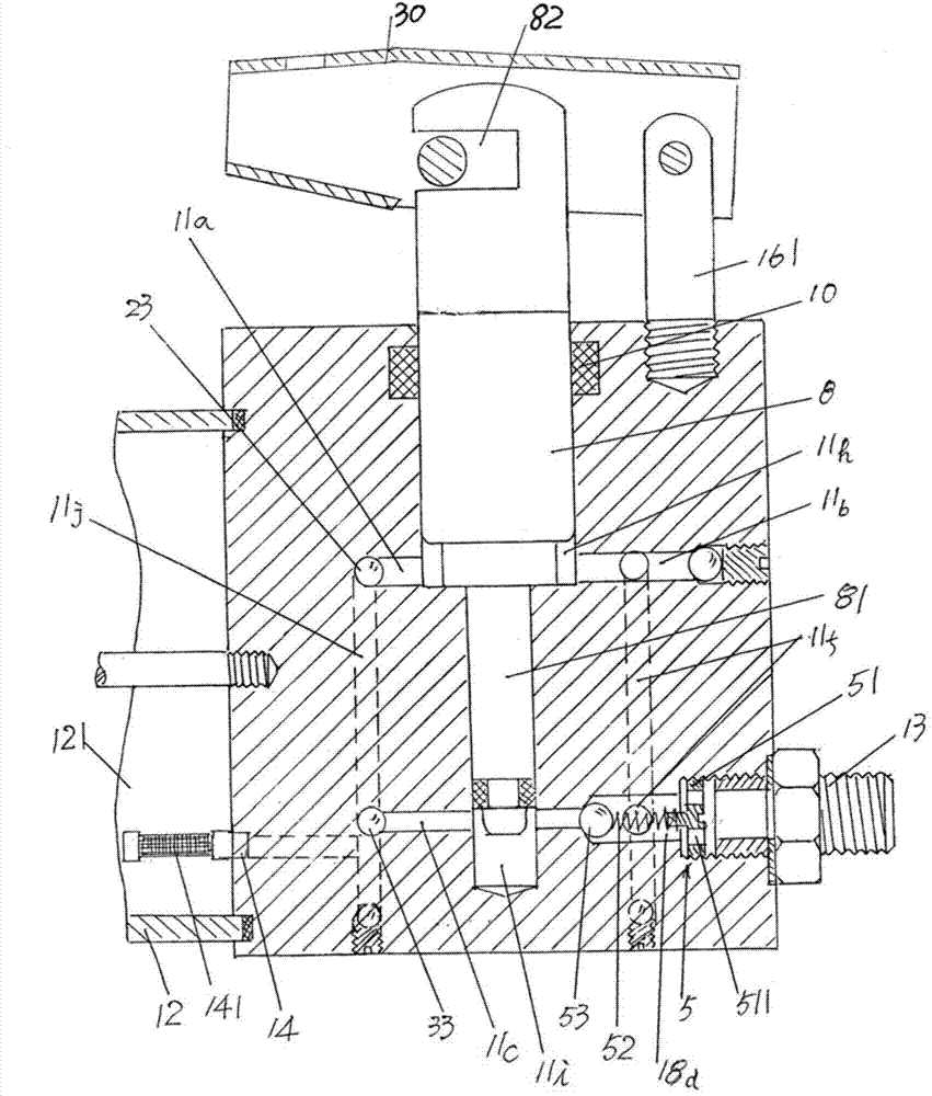
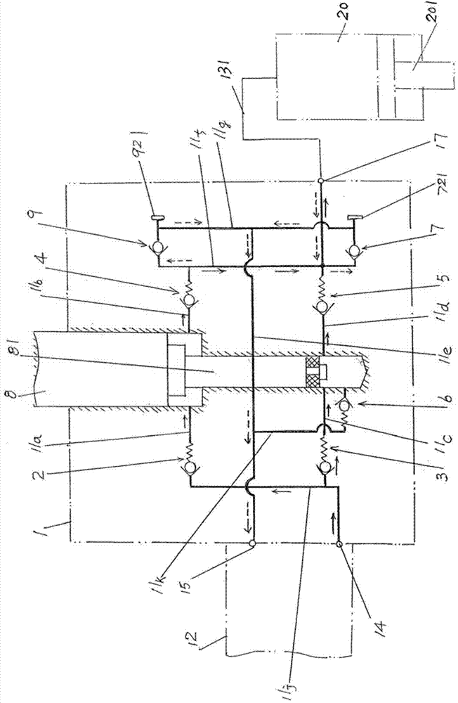

Image

  • Valve body structure for manually adjusting fast speed or slow speed of oil pumping
  • Valve body structure for manually adjusting fast speed or slow speed of oil pumping
  • Valve body structure for manually adjusting fast speed or slow speed of oil pumping

Examples


Embodiment Construction

[0018] In order to enable the examiners of the patent office, especially the public, to understand the technical essence and beneficial effects of the present invention more clearly, the applicant will describe in detail the following in the form of examples, but none of the descriptions to the examples is an explanation of the solutions of the present invention. Any equivalent transformation made according to the concept of the present invention which is merely formal but not substantive shall be regarded as the scope of the technical solution of the present invention.

[0019] In the following descriptions, the applicant refers to the orientation concepts of left end, right end, top, bottom, front side and rear side, etc., which are all for the position state shown in the figure, so it cannot be understood as the basis for the present invention. Program limitations.

[0020] See Figure 1 to Figure 3 , a valve seat 1 is given, and an oil storage cylinder 12 ( figure 2 wit...


PUM


Abstract

The invention relates to a valve body structure for manually adjusting fast speed or slow speed of oil pumping, which belongs to the technical field of hydraulic drive devices. The valve body structure comprises a valve seat, a big pump oil-taking channel check valve, a small pump oil-taking channel check valve, a big oil outlet channel check valve, a small oil outlet channel check valve, a small pump pressure regulating valve, an operating cylinder pressure relief oil return valve, a big pump core, and a big pump core pressure relief manual manipulation valve, wherein an oil storage cylinder is arranged on the left end of the valve seat in a matching manner; an oil outlet connector is arranged on the right end of the valve seat in a matching manner; a big pump core cavity oil-taking channel, a big pump core cavity oil outlet channel, a small pump core cavity oil-taking channel, a small pump core cavity oil outlet channel, a main oil return channel, a main oil outlet channel, an oil return channel, a big pump core cavity, a small pump core cavity and an oil-taking channel are arranged on the valve seat; one end of a small pump core cavity overpressure oil return channel is communicated with the main oil return channel; the other end of the small pump core cavity overpressure oil return channel is communicated with the small pump core cavity; the operating cylinder pressure relief oil return valve is located on a channel of the oil return channel on the valve seat; a small pump core is formed on a lower part of the big pump core through shrinkage; the big pump core pressure relief manual manipulation valve is located between the a big oil outlet channel check valve and the operating cylinder pressure relief oil return valve. Oil supply in high pressure and with small oil amount is realized, and the labor-saving effect on operating the big pump core by operators is ensured.

Description

technical field [0001] The invention belongs to the technical field of hydraulic drive devices, and in particular relates to a valve body structure for manually adjusting fast and slow pump oil. Background technique [0002] The above-mentioned valve body structure for manual adjustment of fast and slow pump oil is mainly but not limited to use on jack hydraulic presses to provide hydraulic oil for the dive device of jack hydraulic presses (used to be called workstations, the same below), so as to be operated by The working cylinder column of the working cylinder of the diving device processes the workpiece placed on the workpiece plate bracket (which is installed on the jack hydraulic press and corresponds to the lower part of the cylinder column), such as punching or bending the workpiece ,wait. [0003] The jack hydraulic press mentioned above is a special machine that can play a role in filling gaps compared with large hydraulic presses (also known as hydraulic presses...

Claims


Application Information

Patent Timeline
Patent Type & Authority Patents(China)
IPC IPC(8): F15B13/02
Inventor 李萍唐循申王胜刘羽
Owner CHANGSHU TONGRUN AUTO REPAIRING EQUIP
Learn More