Unit module combination damper

A unit module, air valve technology, applied in the direction of lift valve, valve detail, valve device, etc., can solve the problems of unfavorable production cost and use cost, manufacturing, transportation, installation inconvenience, replacement or maintenance difficulty, etc., to achieve a simplified combined type The effect of air valve structure, compact structure and low production cost

Active Publication Date: 2016-05-11
四川迈铁龙科技有限公司
View PDF7 Cites 0 Cited by
  • Summary
  • Abstract
  • Description
  • Claims
  • Application Information

AI Technical Summary

Problems solved by technology

In the actual application of this type of air valve, there are following deficiencies: 1, the gap air leakage
[0005] In addition to the above two air valves, combined air valves are usually used when they are applied to large and super-large ventilation sections such as tunnels, which are assembled from multiple individual louver air valves, and each individual air valve is It has an independent frame structure and transmission mechanism, so the following problems will arise: 1. The wind resistance area of ​​the combination is the sum of the projected areas of the frame structure of each single air valve, which greatly reduces the effective ventilation area and increases the efficiency of the ventilation joints. In order to reduce; 2. It is necessary to set up a set of linkage transmission mechanism connecting each individual air valve outside the combination, which makes the whole set of combined air valves huge in size and very inconvenient to manufacture, transport and install; 3. When a single unit in the combination When the body air valve fails, it is very difficult to remove it from the assembly for replacement or maintenance; 4. The frame structure of the single air valve is a thick metal profile, and the consumption of metal materials is large, which is not conducive to reducing production costs and usage fees

Method used


Image

  • Unit module combination damper
  • Unit module combination damper
  • Unit module combination damper

Examples


Embodiment Construction

[0025] The present invention will be further described below in conjunction with the accompanying drawings and embodiments.

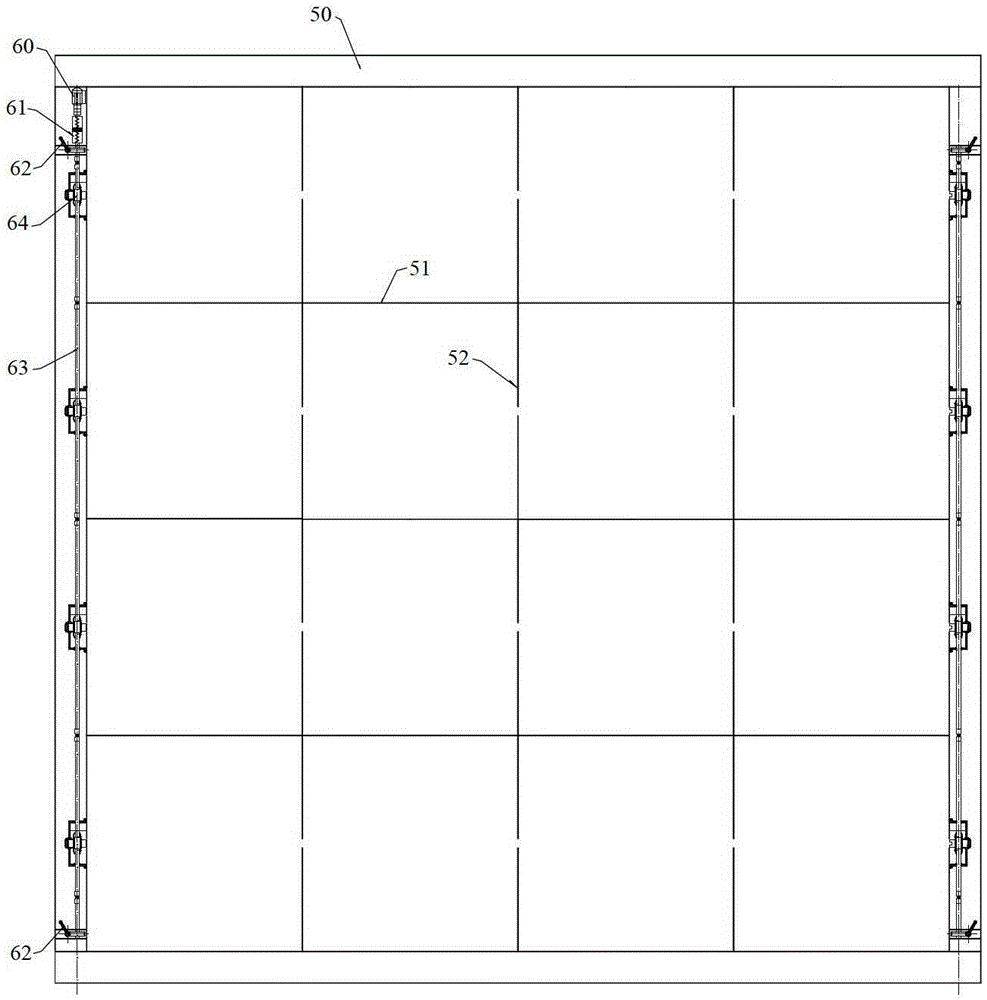
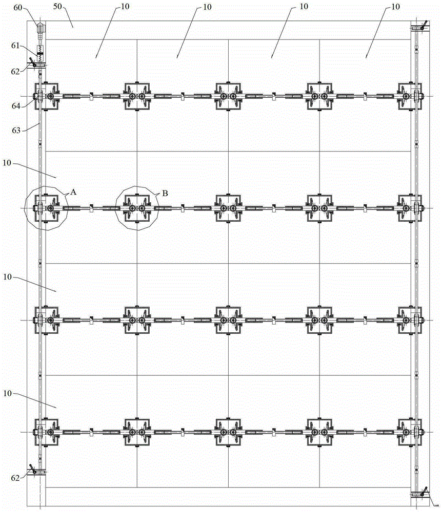
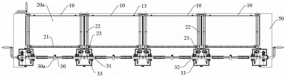
[0026] refer to figure 1 , figure 2 and Figure 8 , the unit module combination damper of the present invention comprises: integral frame 50, and the frame grid formed by parallel transverse plate 51, vertical plate 52 is fixedly arranged in it as the force-receiving structure; Unit module 10, is arranged on each frame grid In the rectangular grid, each unit module 10 has an internal transmission mechanism that drives its blades to open and close, and has a coupling structure 34 that drives and connects the internal transmission mechanisms of adjacent unit modules 10; the linkage device is arranged on the overall frame 50, An internal transmission mechanism for driving each row or row of unit modules.

[0027] The unit module combination damper of the present invention realizes modular combination, and each unit module 10 has an integrated internal ...


PUM


Abstract

A unit module combined air valve comprises an overall frame (50), unit modules (10) and a linkage device. A frame grating formed by parallel transverse boards (51) and longitudinal boards (52) are fixed in the overall frame (50). Each unit module (10) is disposed in the corresponding rectangular lattice of the frame grating and provided with an inner transmission mechanism for driving a vane of the unit module to open and close. Each unit module (10) is further provided with a coupling structure (34) connected with the inner transmission mechanisms of adjacent unit modules (10). The linkage device is disposed on the frame (50) and used for drive the inner transmission mechanisms of each row or each line of unit modules (10).

Description

technical field [0001] The invention relates to an air duct valve for controlling and adjusting the airflow of a ventilation pipeline. Background technique [0002] The air duct valve is a commonly used device in various ventilation pipelines. Its basic function is to completely block or completely open the ventilation pipeline according to the actual needs of the ventilation system, and it can also be partially opened according to the demand to adjust the pipeline. Air flow through. [0003] At present, the most common form of this damper is the louver damper. The basic function of closing, opening or partially opening the ventilation pipeline is realized by the synchronous rotation of multiple sets of blades at different angles. In the actual application of this type of air valve, there are following deficiencies: 1, the slit leaks air. Since the louver air valve is composed of multiple sets of blades, when the air valve is closed, objectively there must be incompletely ...

Claims


Application Information

Patent Timeline
Patent Type & Authority Patents(China)
IPC IPC(8): F16K1/18F16K1/36F16K31/04F16K31/53
Inventor 钟星灿肖健刘勋兵
Owner 四川迈铁龙科技有限公司
Why Eureka
Try Eureka