An electric long slide rail split transmission system

A technology of transmission system and long slide rail, which is applied to movable seats, special positions of vehicles, vehicle parts, etc., can solve problems such as large deflection of screw rods, increase production, and difficulty in analysis of slide rail problems, and achieve extended stroke range, The effect of avoiding abnormal noise and facilitating independent disassembly and assembly operations

Active Publication Date: 2020-02-04
KEIPER SEATING MECHANISMS CO LTD
View PDF3 Cites 0 Cited by
  • Summary
  • Abstract
  • Description
  • Claims
  • Application Information

AI Technical Summary

Problems solved by technology

The traditional screw nut transmission scheme basically cannot meet the transmission requirements of longer strokes due to the excessive deflection of the screw rod under long strokes.
[0004] At the same time, when there is a problem with the operation of the slide rail, the disassembly of the gear box needs to destroy the slide rail assembly. On the one hand, this method is not convenient for the analysis of the problem. On the other hand, whether the gear box is scrapped or not will directly affect the slide rail. Whether it is scrapped or not, indirectly increases the cost of production, maintenance and upgrading, especially for high-cost slide rails such as electric long slide rails, the cost of scrapping will be greater, and the analysis of slide rail problems will become more difficult

Method used


Image

  • An electric long slide rail split transmission system
  • An electric long slide rail split transmission system
  • An electric long slide rail split transmission system

Examples


Embodiment Construction

[0027] The preferred embodiments of the present invention will be described in detail below in conjunction with the accompanying drawings, so that the advantages and features of the present invention can be more easily understood by those skilled in the art, so as to define the protection scope of the present invention more clearly.

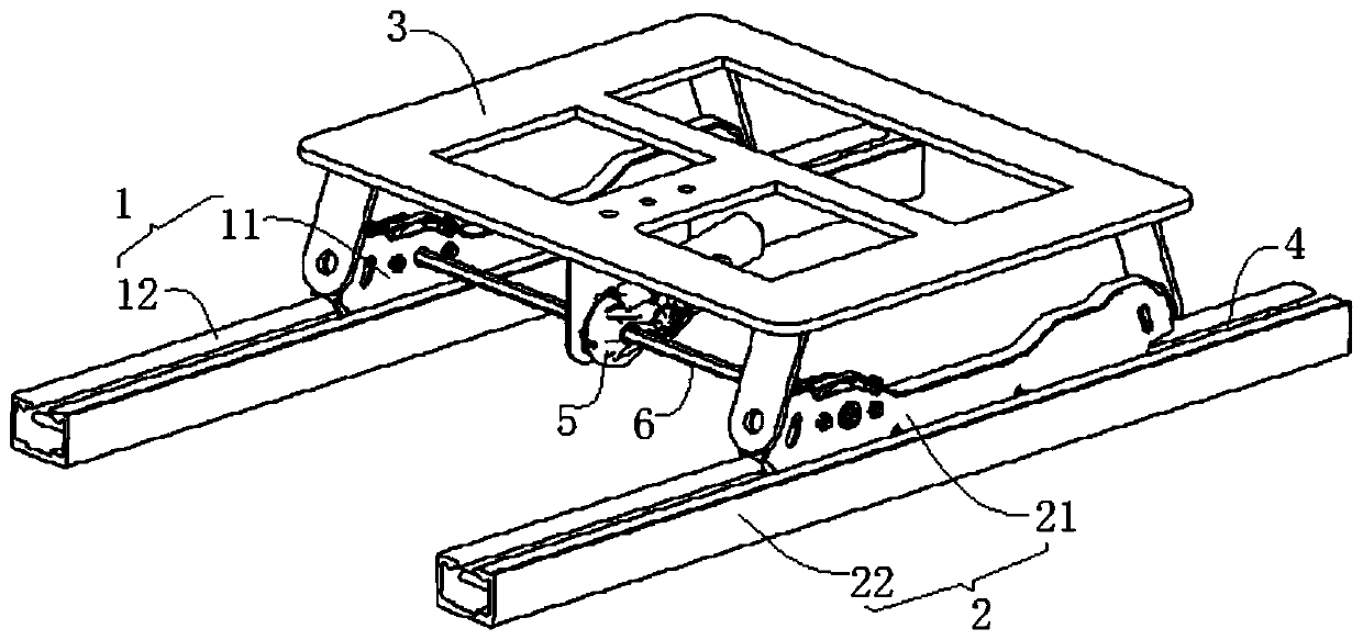
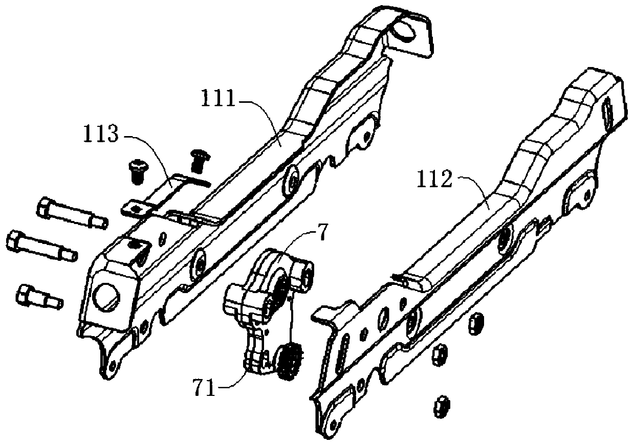
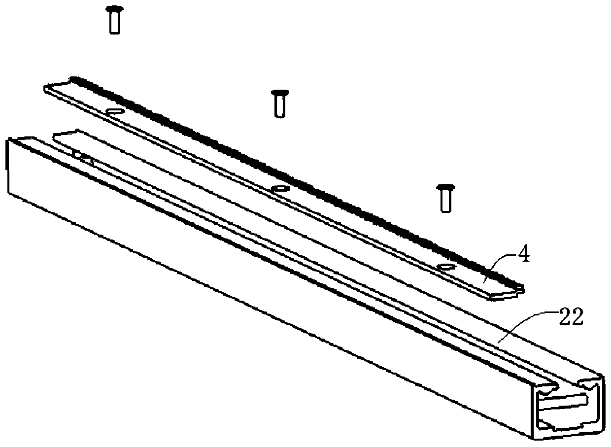
[0028] refer to Figure 1-6 As shown, the electric long slide rail split transmission system of the present invention, the slide rail includes a left rail assembly 1 and a right rail assembly 2, the left rail assembly 1 includes a left upper rail 11 and a left lower rail 12 that are slidably connected, and the right rail assembly Into 2 comprises the upper right rail 21 and the lower right rail 22 of sliding connection, and this system comprises:

[0029] Slide rail connecting bridge 3, left and right sides are respectively fixed on the top of left upper rail 11 and right upper rail 21; Slide rail connecting bridge 3 can guarantee the synchronous...


PUM


Abstract

The invention discloses an electric long slide rail split transmission system. The slide rail includes a left rail assembly and a right rail assembly. The left rail assembly includes a left upper rail and a left lower rail that are slidably connected. Right upper rail and right lower rail, the system includes: slide rail connecting bridge, the left and right sides are respectively fixed above the left upper rail and right upper rail; The module is connected to the lower surface of the middle part of the slide rail connecting bridge; the transmission rod is connected to the output end of the drive module in the middle; the transmission module is respectively fixed inside the upper left rail and the upper right rail, wherein the transmission module includes a casing, a drive gear and The output gear, the output gear includes meshing gears, transmission gears and connecting bolts. The invention avoids the deflection problem of the long screw rod in long-stroke transmission, and effectively avoids the generation of abnormal sound. At the same time, it facilitates the independent disassembly and assembly operation of the transmission module in the slide rail.

Description

technical field [0001] The invention relates to the technical field of car seat slide rails, in particular to an electric long slide rail split transmission system. Background technique [0002] At present, the adjustable slide rails in the front and rear direction of the car seat are divided into two types according to the driving mode: manual adjustment and electric adjustment. Among them, the basic structure of the electric adjustment slide rail is a motor bracket assembly and a pair of slide rail assemblies. The motor bracket assembly includes the drive motor and the bracket structure for fixing the motor. The torque is transmitted to the slide rail through the flexible shaft. The upper side of the slide rail is equipped with a gear box such as a worm gear, and the screw is fixed to the lower rail. Generally, the rotation of the motor is converted into the linear movement of the slide rail through the threaded auxiliary transmission of the nut in the gear box and the scr...

Claims


Application Information

Patent Timeline
Patent Type & Authority Patents(China)
IPC IPC(8): B60N2/02B60N2/07B60N2/075
CPCB60N2/0722B60N2/075B60N2/02253B60N2/02246
Inventor 李启超杨素林蒋红辉范业帝贺龙辉
Owner KEIPER SEATING MECHANISMS CO LTD
Why Eureka
Try Eureka