Detection device for detecting liquid crystal module

A detection device, liquid crystal module technology, applied in nonlinear optics, instruments, optics, etc., can solve the problems of increasing product defect rate, slow production speed, low production efficiency, etc. Production cost and the effect of improving production efficiency

Active Publication Date: 2013-12-18
SUZHOU HUAXING YUANCHUANG TECH CO LTD
View PDF6 Cites 3 Cited by
  • Summary
  • Abstract
  • Description
  • Claims
  • Application Information

AI Technical Summary

Problems solved by technology

The existing method mainly has the following two disadvantages: 1. The detection speed is slow and the production efficiency is low; 2. The connector port on the module to be tested and the connector detection port on the detection substrate are easily damaged, which increases the product defect rate , leading to an increase in production costs
When testing, the connector on the product side is directly buckled on the connector on the contact substrate, and it needs to be completely pressed in, because the connector is relatively small, and the alignment crimping is very difficult to align, and it is easy to crush the connector. When it is opened, the connector The male end and the female end are locked with hooks, which requires force to open. It is easy to disengage the FPC pad PIN pin welded on the product, and in severe cases, the entire connector will fall off. The result of this is The production speed is slow, the product defect rate is high, and the contact substrate is damaged quickly (the life of each connector is limited to 20-50 times when fully connected), and the manufacturing cost is high

Method used


Image

  • Detection device for detecting liquid crystal module
  • Detection device for detecting liquid crystal module
  • Detection device for detecting liquid crystal module

Examples


Embodiment 1

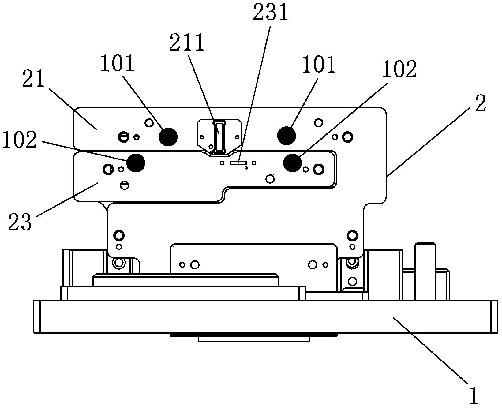
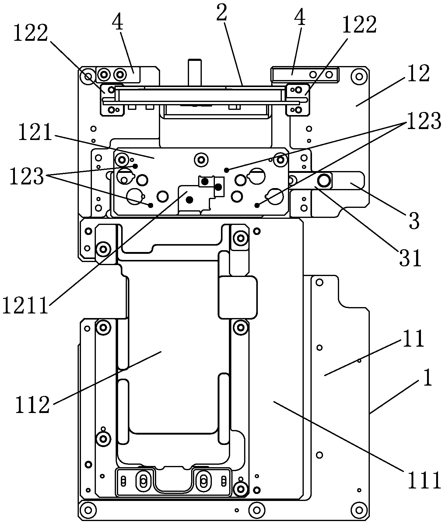
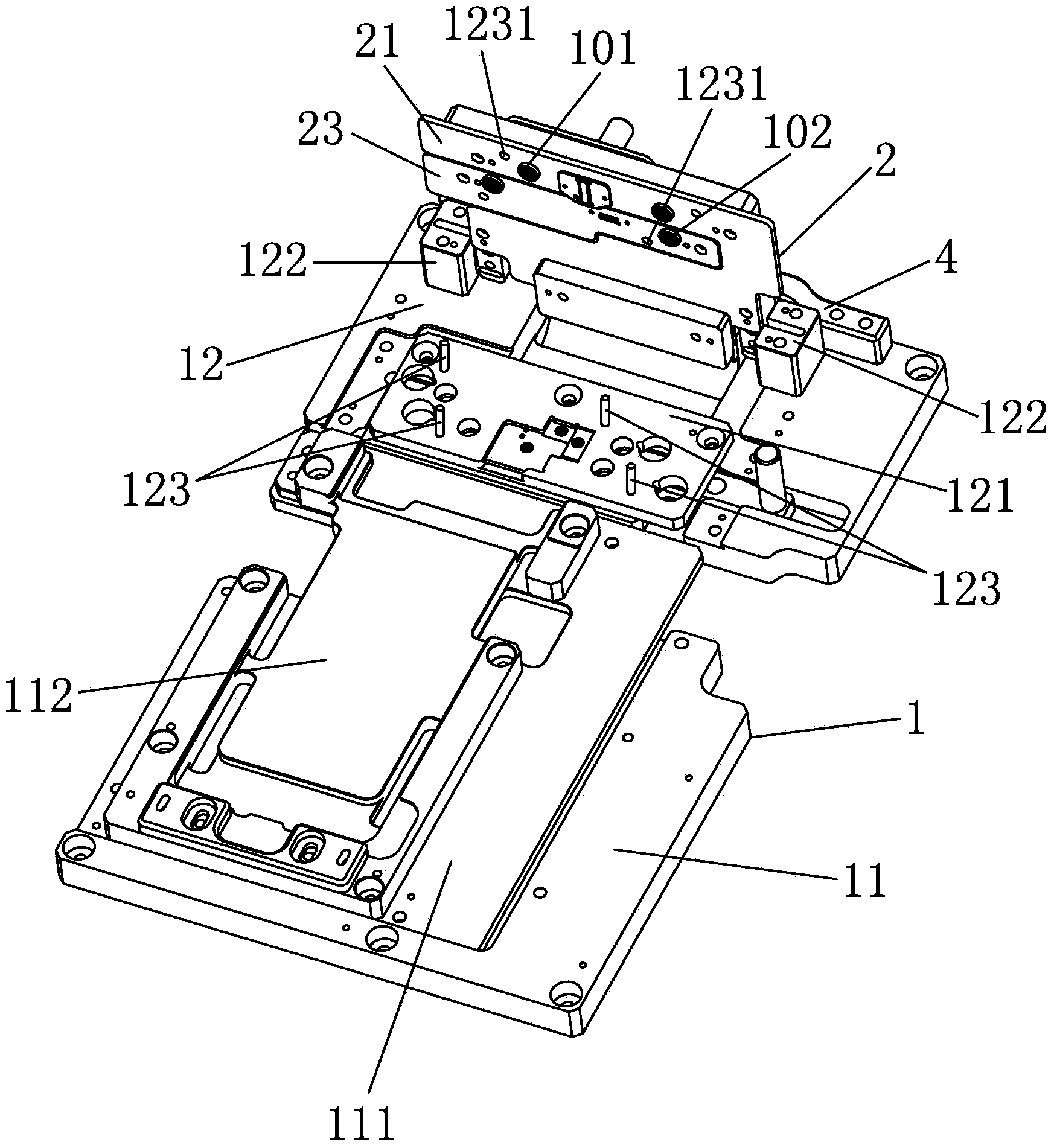
[0081] Such as Figures 1 to 30 As shown, a detection device for liquid crystal module detection, the detection device includes a top plate 1 and a flip assembly 2; the top plate 1 includes a first top plate 11 for placing the module to be tested, and A second floor 12; a backing plate 111 affixed to the first top plate 11 and a module supporting plate affixed to the backing plate 111 are sequentially arranged on the surface of the first top plate 11 112;

[0082] The plate surface of the second second plate 12 is fixed with a limiting plate 121, which is provided with a cavity 1211 for placing the connector port of the module to be tested; the limiting plate 121 is used for positioning the module to be tested. A connector port is used to control the mating height of the connector detection port on the detection substrate and the connector port of the module to be tested; the cavity 1211 is provided with a first magnet 100 for fixing the connector port of the module to be tes...

Embodiment 2

[0111] The difference between this embodiment and Embodiment 1 is that: the first substrate fixing plate and the second substrate fixing plate are arranged side by side in a horizontal direction, the body of the first substrate fixing plate and the body of the second substrate fixing plate are respectively provided with rotating shafts ; The second plate is provided with a rotating shaft seat that matches the rotating shaft.


PUM


Abstract

The invention discloses a detection device for detecting a liquid crystal module. The detection device comprises a top board and an overturning assembly, wherein the top board comprises a first top board and a second top board; the first top board is used for placing a module to be detected; the overturning assembly is arranged on the second top board in a turnover manner and comprises a first detection substrate, a first substrate fixing plate, a second detection substrate and a second substrate fixing plate; the first substrate fixing plate is used for fixing the first detection substrate; the second substrate fixing plate is used for fixing the second detection substrate; a first connector detection port which is used for detecting a connector of the module to be detected is formed in the first detection substrate; a second connector detection port which is used for detecting the connector of the module to be detected is formed in the second detection substrate. In the operation process of the device, the module to be detected is convenient to replace, the damage rate of a connector port in the module to be detected is reduced, the service life of the connector detection ports in the detection substrates is prolonged, and the production efficiency is effectively improved.

Description

technical field [0001] The invention relates to a detection device, in particular to a detection device for liquid crystal module detection. Background technique [0002] Existing liquid crystal module testing fixtures are processed and assembled from black bakelite, sheet metal parts, fixtures, PCB boards, electronic components and various signal lines. It adopts a complete contact method in the detection process, that is, the connector port on the module to be tested is completely pressed into the connector detection port on the contact detection substrate. For products with multiple connector ports, the conduction detection method is also used to detect the crimping of the ports one by one. The existing method mainly has the following two disadvantages: 1. The detection speed is slow and the production efficiency is low; 2. The connector port on the module to be tested and the connector detection port on the detection substrate are easily damaged, which increases the pro...

Claims


Application Information

Patent Timeline
Patent Type & Authority Applications(China)
IPC IPC(8): G02F1/13
Inventor 陈文源曹振军应林华江斌
Owner SUZHOU HUAXING YUANCHUANG TECH CO LTD
Why Eureka
Try Eureka