Pen type cutter

A tool and pen-type technology, which is applied in the field of pen-type tools for testing the film layer on the surface of workpieces, can solve the problems of easy wear of the blade, damage and bluntness of the blade, and high cost, so as to improve the marking efficiency, facilitate replacement, and reduce the cost of use. Effect

Inactive Publication Date: 2016-02-17
SHENZHEN FUTAIHONG PRECISION IND CO LTD
View PDF5 Cites 2 Cited by
  • Summary
  • Abstract
  • Description
  • Claims
  • Application Information

AI Technical Summary

Problems solved by technology

However, the blade is very easy to wear and tear. After drawing a limited number of times, the blade will be damaged and blunt, and the entire blade needs to be replaced, which is costly
In addition, the direction of the cutting edge is determined after the cutting head is processed. For some film tests that require the angle of the cutting edge, the hundred grid knife is no longer applicable, and its versatility is poor.

Method used


Image

  • Pen type cutter
  • Pen type cutter
  • Pen type cutter

Examples


Embodiment Construction

[0017] Embodiments according to the present invention will be described with reference to the drawings. These drawings are all simplified schematic diagrams, which only illustrate the basic structure of the present invention in a schematic manner, so they only show the configurations related to the present invention.

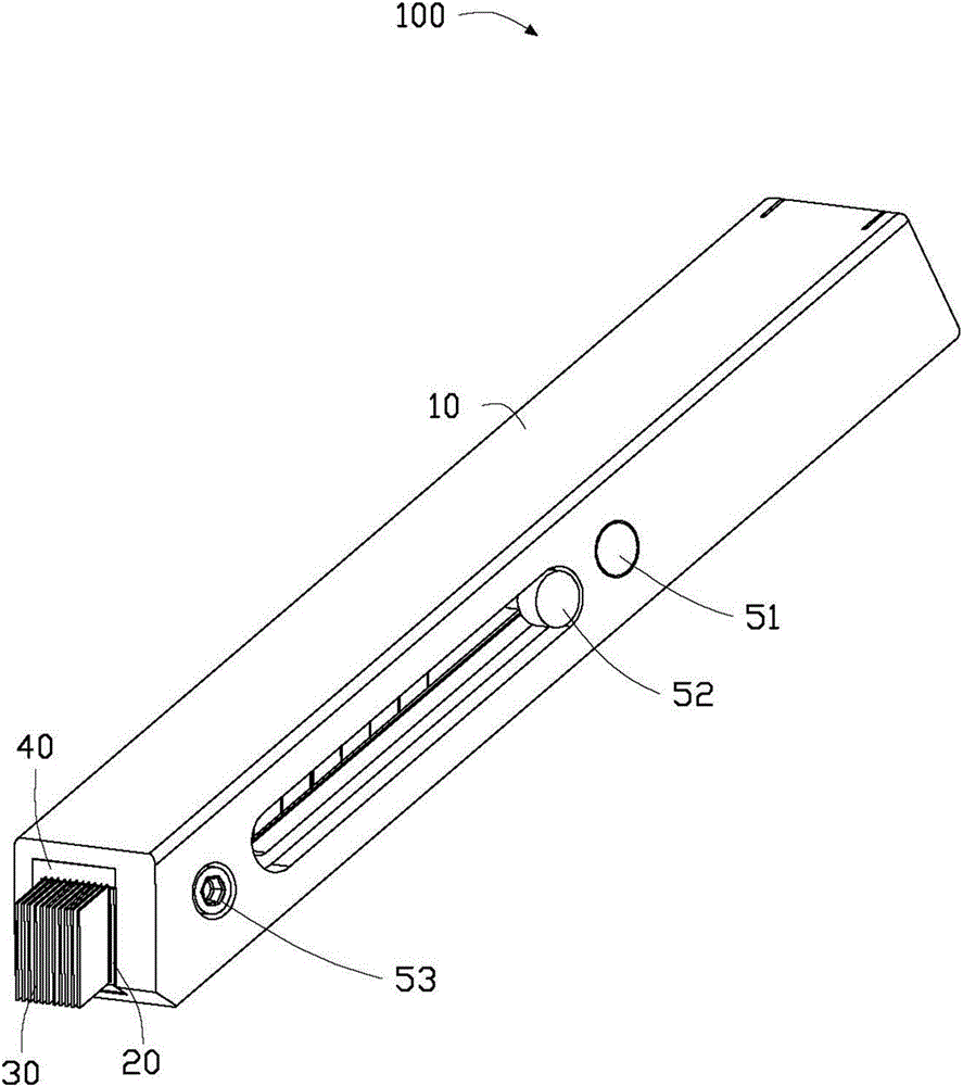
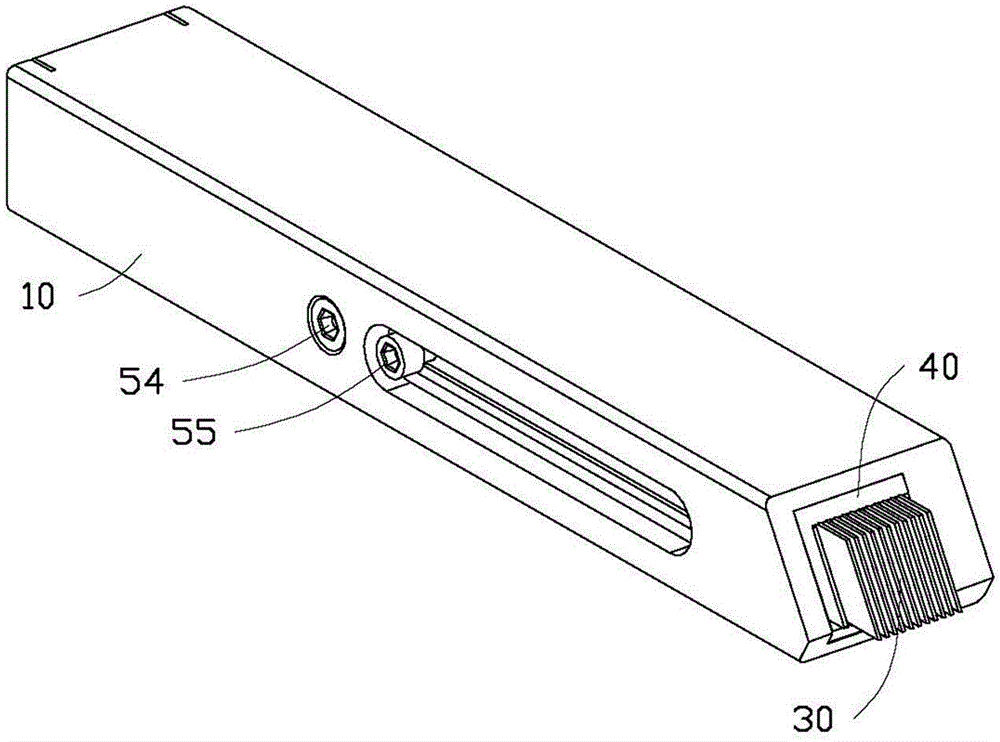
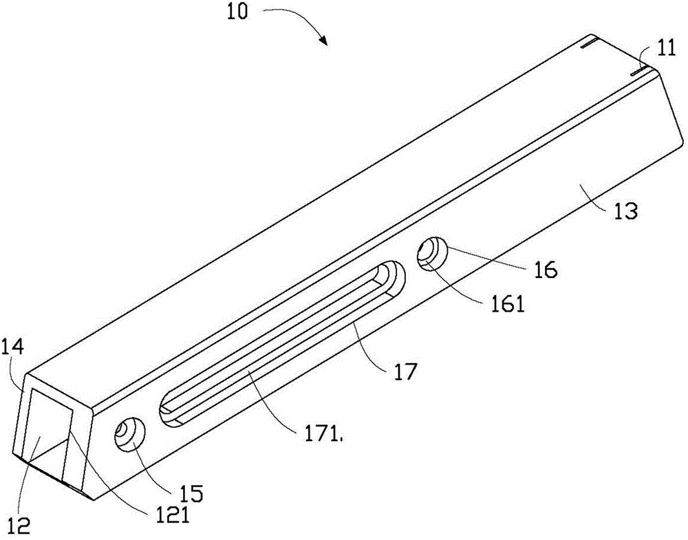
[0018] Please refer to figure 1 and figure 2 , the pen tool 100 of the present invention includes a hollow cylindrical handle 10, a plurality of spacers 20 completely accommodated in the handle 10, a plurality of pads 20 partially accommodated in the handle 10 and spaced apart from the plurality of spacers 20. The blade 30 and the limiting frame 40 located at the port of the handle 10 to limit the sliding of the blade 30 . A plurality of spacers 20 are locked into the knife handle 10 through the spacer locking member 51, and a plurality of blades 30 are arranged at intervals between the plurality of spacers 20 and locked into the knife handle 10 through the b...


PUM


Abstract

The invention relates to a pen type cutter. The pen type cutter comprises a cutter handle with a containing cavity and a plurality of blades contained in the containing cavity, and an opening is formed in the end of the cutter handle. The pen type cutter further comprises a plurality of gaskets contained in the containing cavity, and the multiple gaskets and the multiple blades are arranged alternatively and are fixedly locked into the containing cavity in a detachable manner. By means of the pen type cutter, the lineation efficiency can be effectively improved, and the using cost can be lower.

Description

technical field [0001] The invention relates to a pen-type tool, in particular to a pen-type tool for testing the film layer on the surface of a workpiece. Background technique [0002] At present, in order to evaluate the adhesion of the film layer after the surface of the workpiece is treated (such as spraying or coating), according to the standard ISO2409-2007, it is necessary to use a blade to vertically draw one hundred pieces with an area of ​​about one square millimeter on the surface of the film layer. square grid (also known as a hundred grid), and use a brush to remove surface debris. Then, use a special adhesive tape to stick it on the grid, pull up the tape quickly after a period of time, and observe the peeling off of the film layer in the area of ​​the grid under a magnifying glass, so as to judge the adhesion degree of the film layer to the substrate. [0003] In the prior art, in order to realize the drawing of a hundred grids, one way is to use a hundred gr...

Claims


Application Information

Patent Timeline
IPC IPC(8): B25H7/04
CPCG01N19/04B26B5/002B26B5/008B26B29/02
Inventor 梁荣振郑国增胡隽武崔磊
Owner SHENZHEN FUTAIHONG PRECISION IND CO LTD
Why Eureka
Try Eureka