Electromagnetic induction welding of plastic pipe distribution systems

A technology of induction welding and electromagnetic induction, which is applied in the direction of induction heating, pipeline connection arrangement, induction heating device, etc., and can solve problems such as weak welding

Inactive Publication Date: 2013-12-18
HULIOT (A C S) LTD
View PDF7 Cites 6 Cited by
  • Summary
  • Abstract
  • Description
  • Claims
  • Application Information

AI Technical Summary

Problems solved by technology

But the electromagnetic induction coil assembly 10 does not enclose the inductio

Method used


Image

  • Electromagnetic induction welding of plastic pipe distribution systems
  • Electromagnetic induction welding of plastic pipe distribution systems
  • Electromagnetic induction welding of plastic pipe distribution systems

Examples


Embodiment Construction

[0036] Induction Weldable Fittings

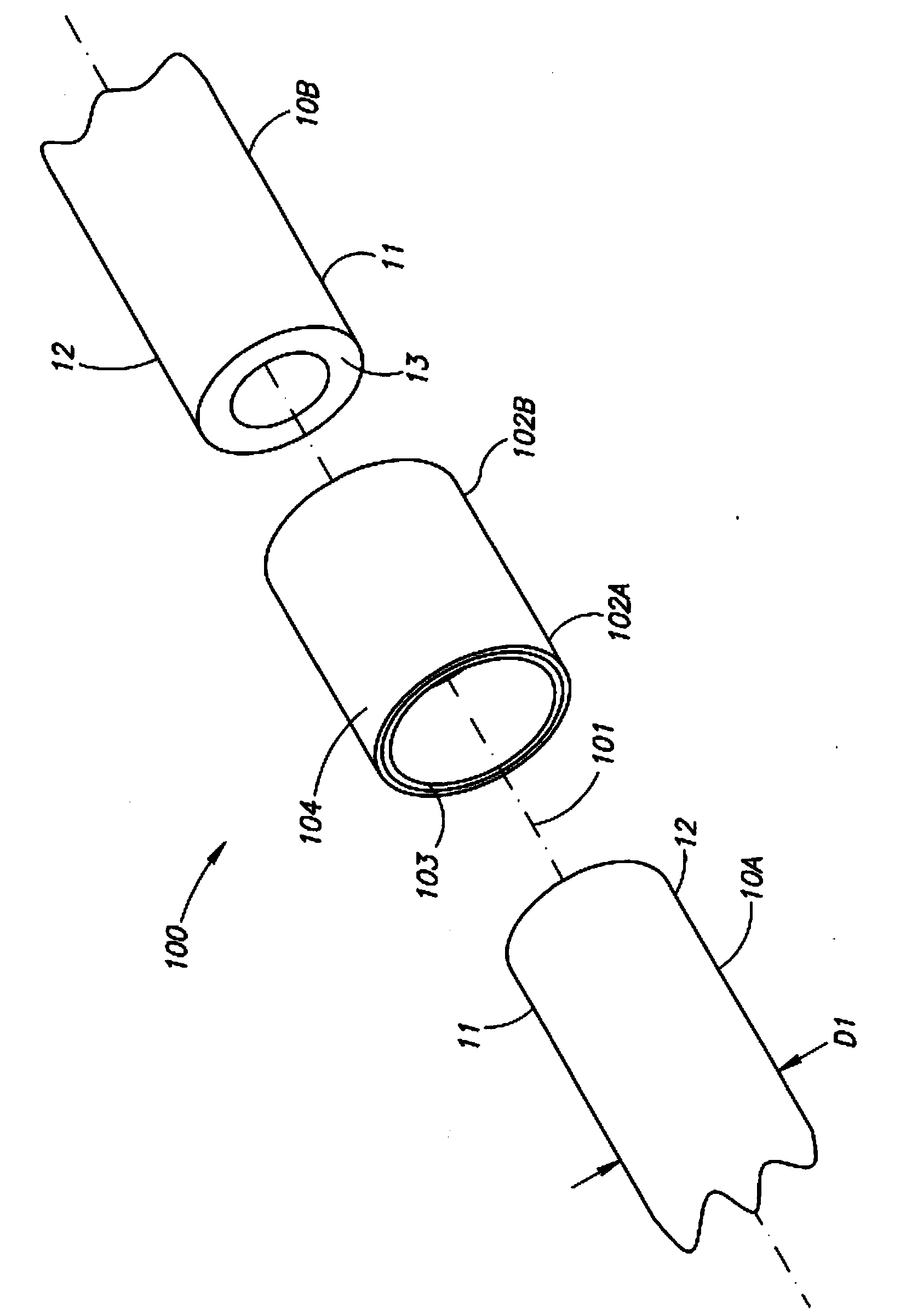
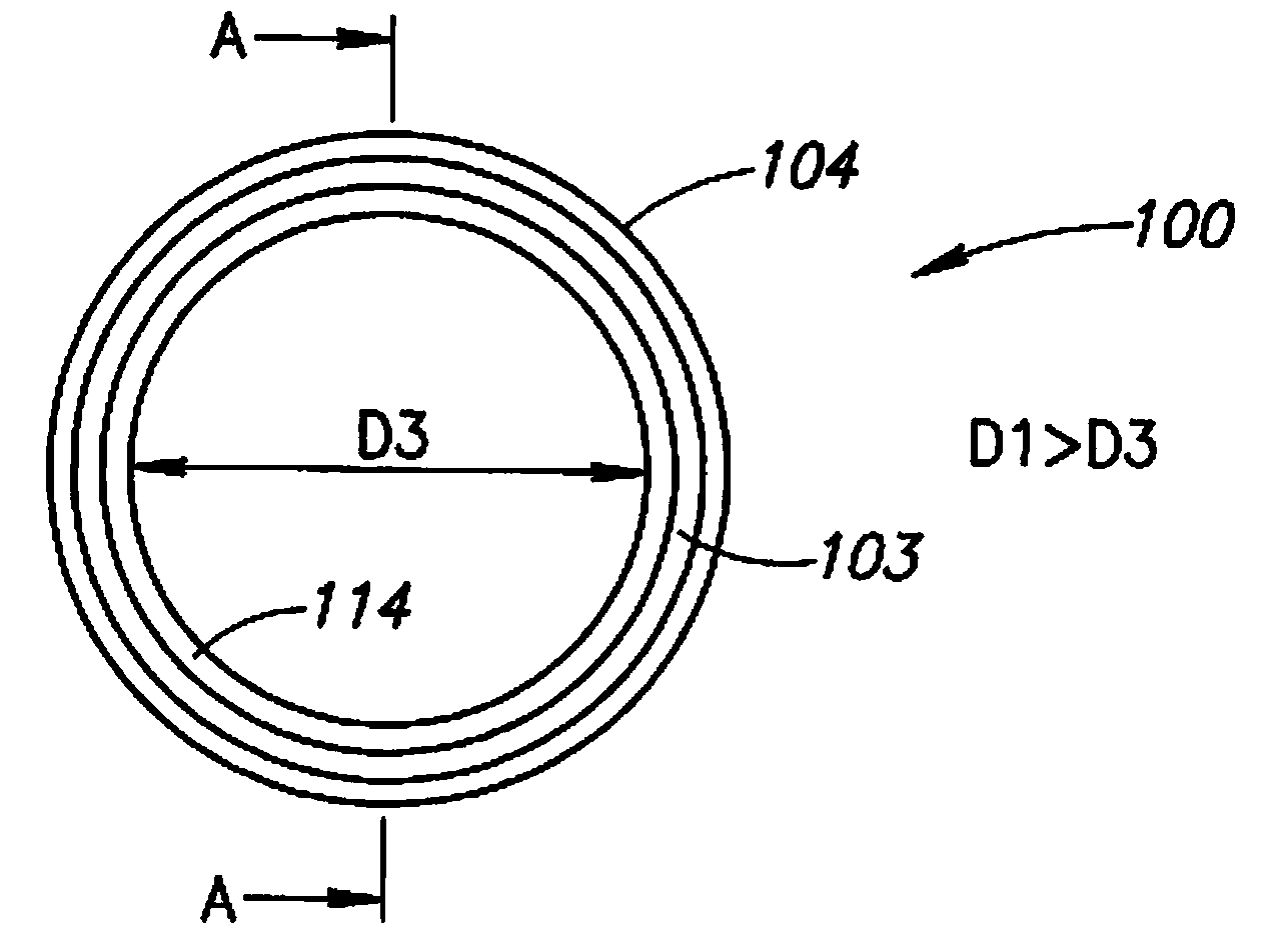
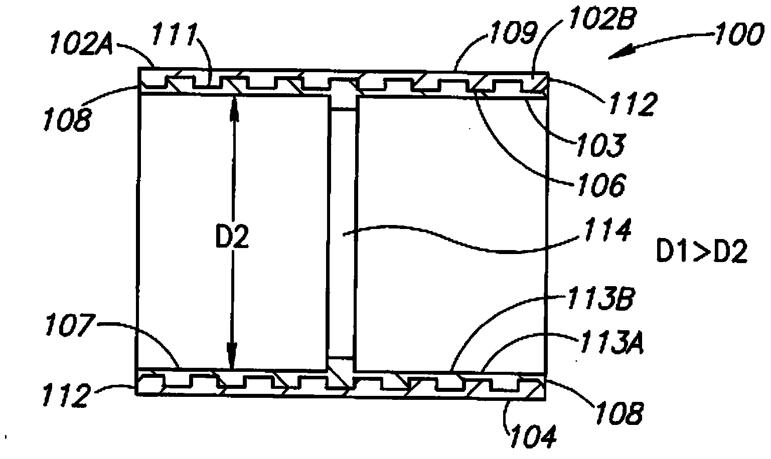
[0037] Figure 1-Figure 4An induction weldable pipe fitting 100 is shown for electromagnetic induction welding to a pair of plastic pipes 10A and 10B. Plastic pipes can be made entirely of a single plastic or have multiple layers. Multilayer compositions are used to provide a better combination of mechanical and chemical properties such as weight, stiffness, strength, chemical resistance, operating pressure, operating temperature, etc. The plastic tube 10 is usually of the same material. The outer diameter D1 of the plastic tube 10 is typically in the range of 10 mm to 30 mm. The plastic tube 10 has a tube end 11 . The pipe end 11 has a circumferential outer pipe end surface 12 and an annular pipe end surface 13 .

[0038] The induction weldable pipe joint 100 has a longitudinal pipe joint shaft 101 and includes two opposite induction weldable pipe sockets 102A and 102B, each for force-sliding insertion of the plastic pipe end 11 the...


PUM


Abstract

Electromagnetic induction welding of plastic pipe distribution systems including inter alia induction weldable pipe connectors (100) each having at least one induction weldable pipe socket (102). The induction weldable pipe sockets include a solid metal susceptor sleeve (104) enveloping a plastic solder lining (103). Electromagnetic induction coil assemblies (200) for clamping on induction weldable pipe sockets (100).

Description

technical field [0001] The present invention relates to induction weldable pipe joints and electromagnetic induction coil assemblies for electromagnetic induction welding of plastic pipe wiring systems for fluid transport in residential, commercial, and industrial pipeline systems. Background technique [0002] Induction welding applies electromagnetic induction to a susceptor to melt the plastic parts of the plastic pipe wiring system. [0003] European Patent Publication No. 0294008 exemplifies and describes weldable sleeves and methods and apparatus for making such sleeves, as well as methods for connecting the sleeves to penetrating pipe components. The induction weldable sleeve 2 includes an induction heatable liner 3 adjacent to the inner wall of the socket. The sleeve 2 can be produced by feeding an induction heatable liner into the transverse extrusion head of the extruder 21 and cutting the extruded tube with the liner 3 from the extruder to obtain the sleeve 2 . ...

Claims


Application Information

Patent Timeline
IPC IPC(8): B29C65/36H05B6/10H05B6/44
CPCB29C65/3656B29C65/3668B29C65/368B29C66/5221B29C66/52292B29C66/52295B29C66/972B29C66/1222B29C66/1224B29C66/735B29C66/83241B29C66/5344B29C66/52298B29C66/81423F16L47/02B29C66/72321B29K2995/0008B29C66/71B29C66/8264B29C66/8286B29C66/8221B29C65/561B29K2023/065B29K2027/06B29K2023/12B29K2023/0691F16L13/0209
Inventor 吉迪恩·霍尔曼
Owner HULIOT (A C S) LTD
Why Eureka
Try Eureka