

Rigid core for tire formation
A rigid core and tire molding technology, applied in tires, applications, household appliances, etc., can solve problems such as insufficient joint strength, no consideration of rubber inflow, and reduced durability of core segments
Active Publication Date: 2013-12-18
SUMITOMO RUBBER IND LTD
View PDF7 Cites 20 Cited by
- Summary
- Abstract
- Description
- Claims
- Application Information
AI Technical Summary
Problems solved by technology
However, in this case, there is a problem that the strength of the connecting portion becomes insufficient due to repeated large-scale thermal expansion, and the durability of the core segment decreases.
In addition, the above scheme still does not consider the problem of rubber flowing into the exhaust passage
Method used
View moreImage
Smart ImageViewing Examples

Examples
Embodiment
[0062] In order to confirm the effect of the present invention, a core body for forming a pneumatic tire having a tire size of 195 / 65R15 was trial-produced based on the specifications in Table 1. In addition, when forming a pneumatic tire using this core body, the state where rubber flows into the vent groove, the sintered state where the inflowing rubber is sintered and adheres to the wall surface of the groove, and the generation of air pockets due to the deterioration of the exhaust performance due to sintering status were evaluated separately.
Login to View More PUM
 Abstract
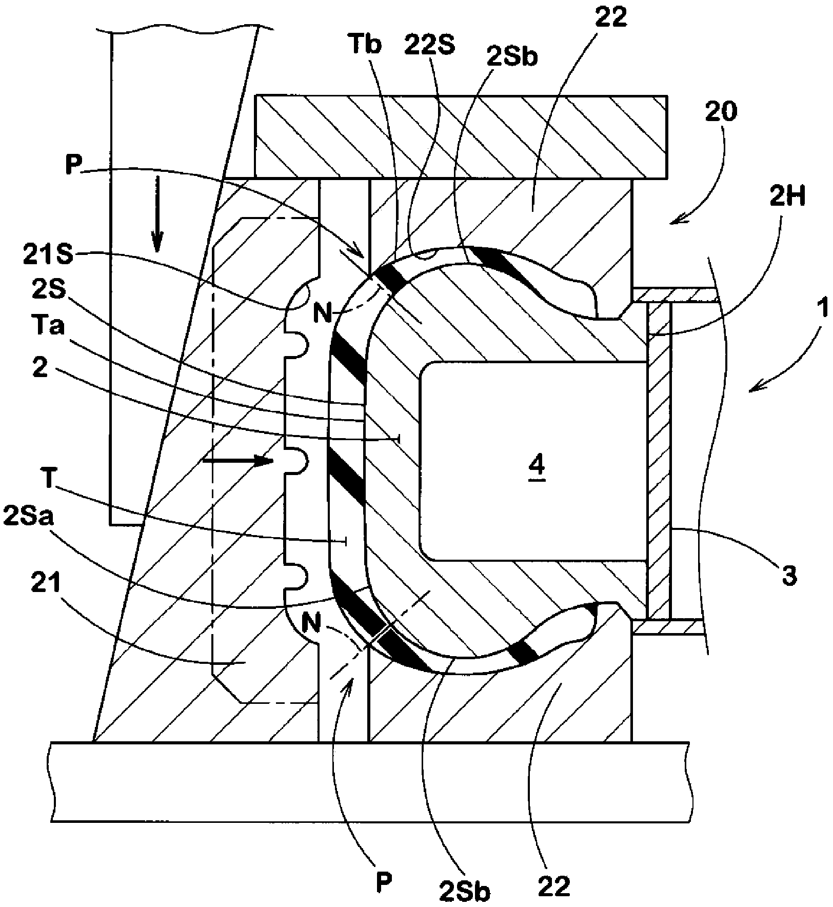
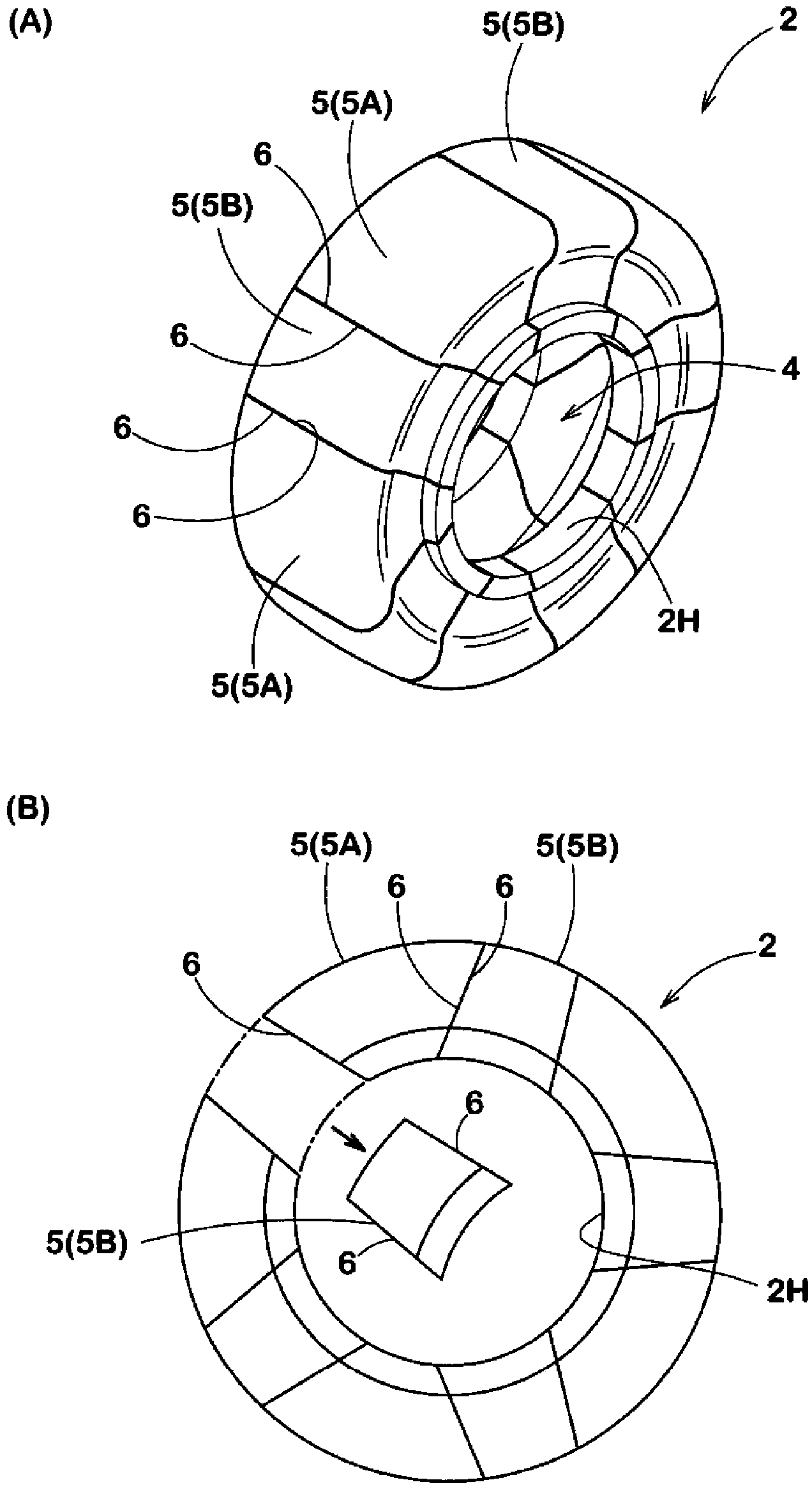
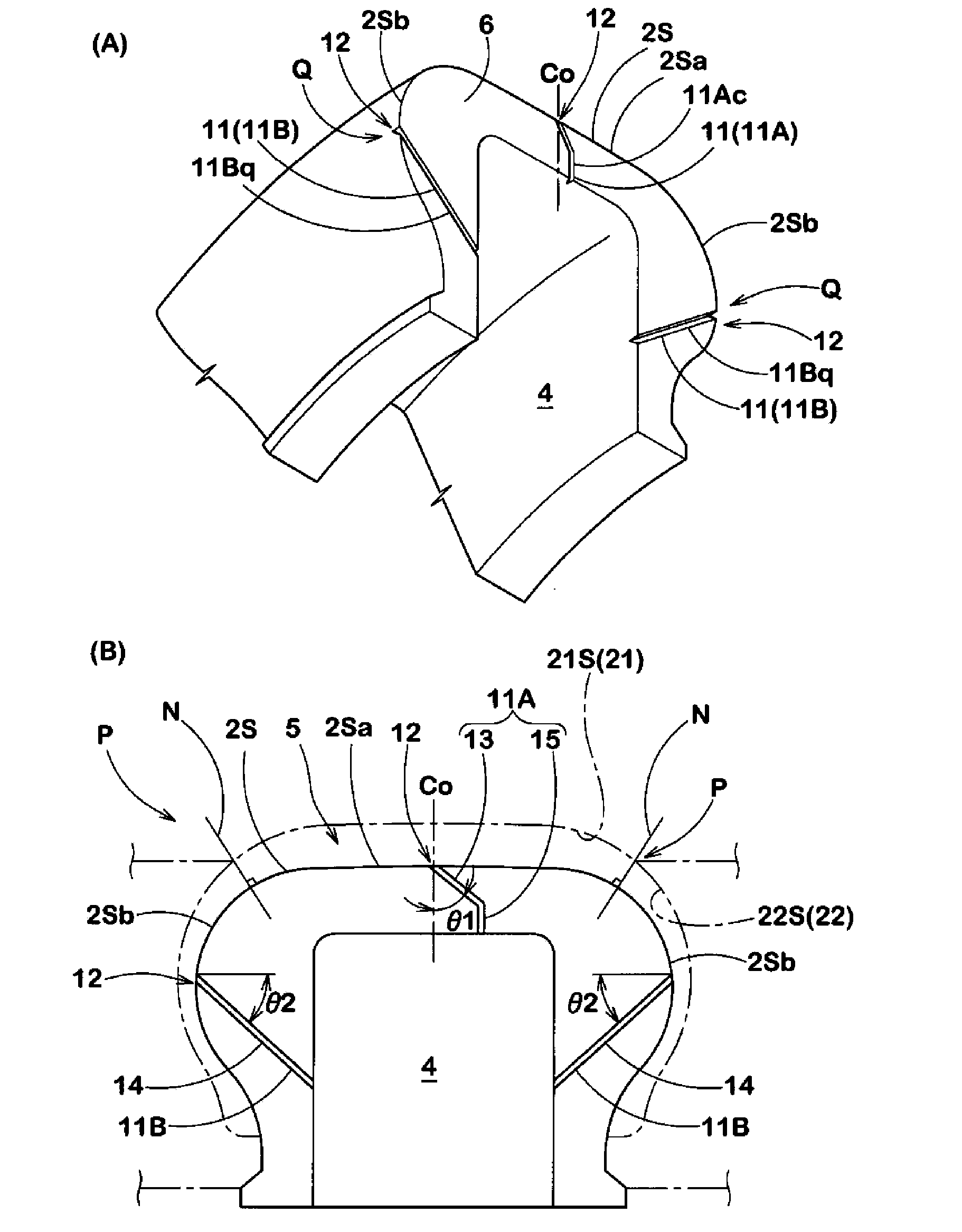
In order to suppress inflow of rubber to an exhaust groove, a core body comprises a plurality of core segments divided in the circumferential direction, and an exhaust grooves having an open end opening in a core-side tire molding face are arranged on the mating face of at least one of core segments adjacent in the circumferential direction. The exhaust groove comprises a tread exhaust groove, the open end of which opens in a portion of a core-side tread molding face, and / or a side exhaust groove which opens in a portion of a core-side side molding face. The tread exhaust groove has an inclined groove portion extending at an angle (theta1) in relation to the radial direction of the tire from the open end, and the side exhaust groove has an inclined groove portion extending at an angle (theta2) in relation to the axial direction of the tire from the open end.
Description
technical field [0001] The present invention relates to a rigid core for forming a tire in which vent grooves are formed on joint surfaces of core segments. Background technique [0002] In recent years, in order to improve tire forming accuracy, a tire forming method using a rigid core (hereinafter, sometimes referred to as a core processing method) has been proposed (for example, refer to Patent Documents 1 and 2). The rigid core includes a core main body having an outer shape conforming to a shape of a tire inner cavity surface of a vulcanized tire. Then, a raw tire is formed by affixing tire constituent members sequentially to the core main body. The green tire is put into a vulcanization mold together with a rigid core, whereby the green tire is vulcanized and molded by being sandwiched between a core body as an inner mold and a vulcanization mold as an outer mold. [0003] Such as Figure 7 As shown in (A), in order to disassemble and remove the core body a from the ...
Claims
Login to View More Application Information
Patent Timeline
 Patent Type & AuthorityApplications(China)
IPC IPC(8): B29D30/12B29C33/76B29C35/02
CPCB29D30/12
Inventor小原圭
OwnerSUMITOMO RUBBER IND LTD