
Larva-migration-free beehive honey collecting device

A technology of moving insects and collecting pulp, which is applied in beehives, beekeeping, applications, etc., can solve the problems of decreased egg production of queen bees, affecting the output of royal jelly, and non-approval.

Inactive Publication Date: 2015-03-25
常熟市陶氏养蜂器具有限公司
View PDF6 Cites 0 Cited by
  • Summary
  • Abstract
  • Description
  • Claims
  • Application Information

AI Technical Summary

Problems solved by technology

[0006] CN201393466Y provides a "quick worm moving tool". According to the description of the 2nd line to the 12th line on page 4 of the specification of this patent, it can be known that the patent is the cavity formed by the bottom of the Wangtai base strip as the basis for the worker bees to build a nest. However, due to the cavity There is a certain distance between them, which not only violates the nesting habits of bees, but also reduces the utilization rate of the entire comb by 50%, so the egg production of the queen bee also decreases significantly, which also affects the output of royal jelly
[0007] In summary, although the above-mentioned patents except CN100350834C have provided the enlightenment of adopting the ovum extraction plug to get ovum, because the center distance between the adjacent ovum extraction plugs formed on the ovum extraction plug strip and the distance between the adjacent ovum extraction plugs on the royal jelly platform base The center-to-center distances of adjacent holes are consistent, and the holes on the royal jelly platform are larger than the holes on the spleen (because the body shape of the aforementioned queen bee is larger than that of the worker bees), and because the holes on the spleen are composed of The holes for the queen bee to lay eggs tend to have no spacing, so if the spacing between adjacent egg-taking plugs is consistent with the nest holes on the spleen, it cannot be consistent with the holes on the royal jelly platform, and vice versa However, it can be seen that in the prior art, the spacing between the egg-taking plugs on the egg-taking plug strip is designed to be one-by-one structure, that is, the distance between adjacent egg-taking plugs is just the diameter of one egg-taking plug, so as to meet the Corresponding holes on the base of royal jelly platform is a last resort design method. The reason why it is called this is because the nest holes on the whole honeycomb appear to be filled with egg-taking plugs row by row. live, that is, the utilization rate of the aforementioned honeycomb is only 50%
The unfavorable factor that this kind of design mode produces also is; Although the queen bee can recognize the honeycomb on the comb that has just been used and lay eggs to it, but when laying eggs for the second time or the next time, it will not recognize it, because the queen bee will not recognize it when laying eggs. It gradually extends from the center to the surroundings in a spiral shape to form a complete spawning area. For those sporadic empty nests that are separated by surrounding nests with eggs or larvae, the queen bee will not lay eggs in it, especially In the case that there is a capping spleen around (6-7 days after the eggs hatch into larvae, the worker bees will cover the nest with beeswax), the queen bee will not lay eggs on the entire comb until The capped spleen begins to emerge into adult bees, and the queen bee continues to lay eggs in the comb

Method used


Image

  • Larva-migration-free beehive honey collecting device
  • Larva-migration-free beehive honey collecting device
  • Larva-migration-free beehive honey collecting device

Examples


Embodiment Construction

[0028] In order to enable the examiners of the patent office, especially the public, to understand the technical essence and beneficial effects of the present invention more clearly, the applicant will describe in detail the following in the form of examples, but none of the descriptions to the examples is an explanation of the solutions of the present invention. Any equivalent transformation made according to the concept of the present invention which is merely formal but not substantive shall be regarded as the scope of the technical solution of the present invention.

[0029] What the applicant needs to explain is that in the following descriptions, all directional or directional concepts such as up, middle, down, left, middle, right, front and back are based on the position status of the current illustration. Therefore, it cannot be construed as a specific limitation to the solution of the present invention.

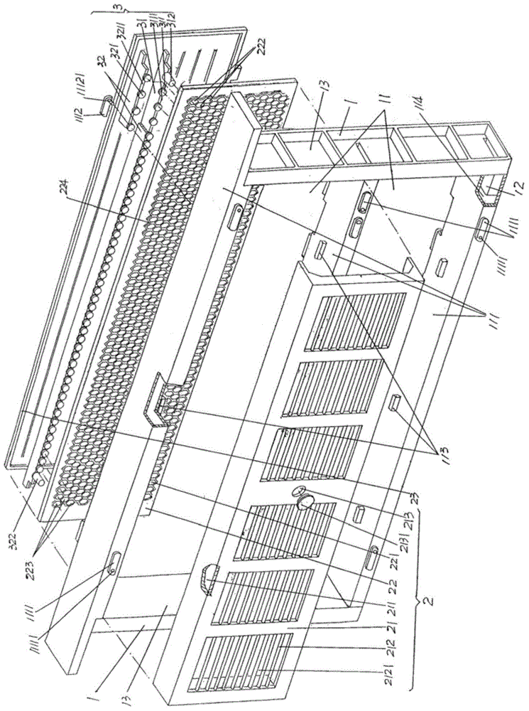
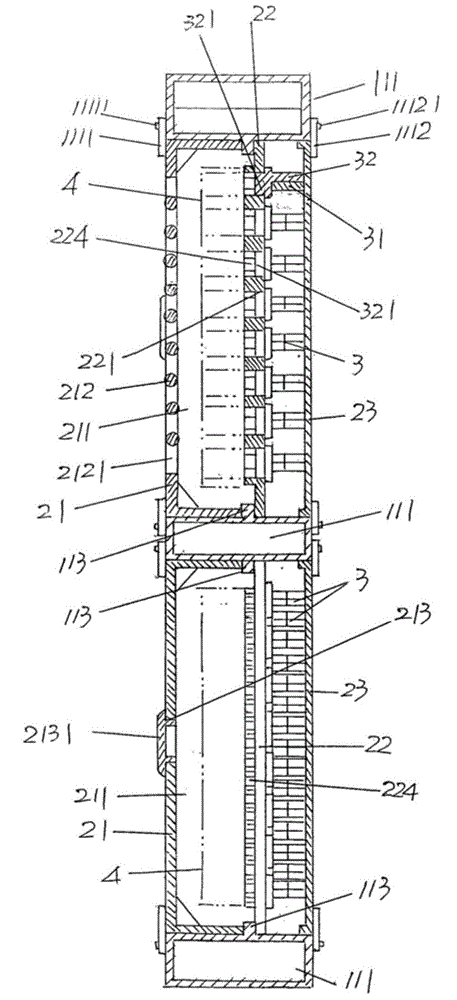
[0030] See figure 1 and figure 2 , the spawning room frame 1...


PUM


Abstract

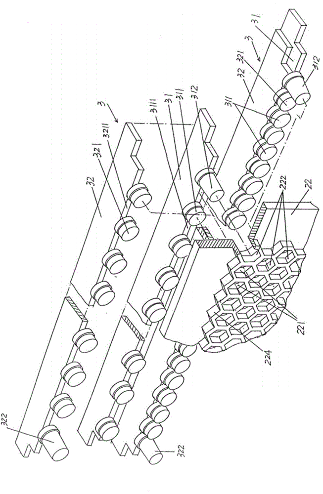
The invention belongs to a bee-keeping appliance, and relates to a larva-migration-free beehive honey collecting device comprising a spawning chamber frame, a spawning chamber and egg collection mechanisms. The spawning chamber frame is provided with a spawning chamber accommodating cavity, and the spawning chamber is composed of queen excluders, a honeycomb and an egg collection plug strip supporting and protecting plate. The larva-migration-free beehive honey collecting device is characterized in that the number of the egg collection mechanisms is equal to that of rows of honeycomb cells on the honeycomb, each egg collection mechanism comprises a first egg collection plug strip and a second egg collection plug strip, a first egg collection plug and a second egg collection plug are formed in the length directions of each first egg collection plug strip and each second egg collection plug strip, when each first egg collection plug and the corresponding second egg collection plug cling to each other, the first and second egg collection plugs on each first egg collection plug strip and each second egg collection plug strip extend into one second egg collection plug and one first egg collection plug which are adjacent on the second and first egg collection plug strips, the sum of the first and second egg collection plugs in one group is equal to the number of the honeycomb cells in one row of the honeycomb, and the egg collection plug strip supporting and protecting plate contacts with one sides, back to the honeycomb, of the first and second egg collection plug strips. Missing of egg collection I prevented, and injury to larvae in the larva migration process is avoided.

Description

technical field [0001] The invention belongs to the technical field of beekeeping appliances, and in particular relates to a beehive free-moving insect slurry collection device. Background technique [0002] As known in the beekeeping industry, the necessary way to produce royal jelly is to transfer the larvae hatched from the fertilized eggs produced by the queen bee on the honeycomb to the holes on the royal jelly base (also known as the royal jelly base strip) (the royal jelly base strip) Move wormhole, hereinafter the same), then worker bees just diligently and constantly secrete jelly in the hole on the royal jelly platform with larvae, and after a few days, the beekeeper collects royal jelly from the platform again. [0003] It can be seen from the above description that there is a worm transfer link in the process of producing royal jelly, that is, there is a link of transferring the larvae on the honeycomb to the royal jelly platform. Furthermore, as known in the in...

Claims


Application Information

Patent Timeline
Patent Type & Authority Patents(China)
IPC IPC(8): A01K47/06
Inventor 陶云岐陶志军
Owner 常熟市陶氏养蜂器具有限公司
Learn More