Pressure ware

A pressure device and pressure head technology, applied in the direction of presses, stamping machines, manufacturing tools, etc., can solve the problems of inconvenient operation, poor mobility, unfavorable disassembly, etc., and achieve simple assembly, simple working principle, and low price Effect

Inactive Publication Date: 2013-12-25
GUIZHOU UNIV
View PDF6 Cites 4 Cited by
  • Summary
  • Abstract
  • Description
  • Claims
  • Application Information

AI Technical Summary

Problems solved by technology

At present, most of the pressure devices on the market are pneumatic or electric, and the structure is complicated. Because o

Method used


Image

  • Pressure ware
  • Pressure ware
  • Pressure ware

Examples


Example Embodiment

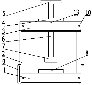
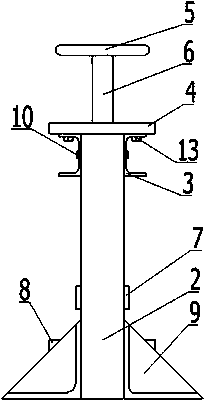
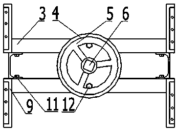
[0016] like Figure 1 to Figure 6 As shown, a pressure device includes a bottom support 1, a vertical support 2 and a support base 9 on both sides of the bottom support 1, an upper support 3 at the top of the longitudinal support 2, a cylindrical spacer 4 above the upper support 3, and a screw rod 6 vertical Through the block 4, its upper and lower ends are respectively connected with the handwheel 5 and the pressure head 7, and the cylindrical platform 8 is directly below the pressure head 7, and the platform 8 is fixed on the bottom support 1. The bottom support 1, the longitudinal support 2 and the upper support 3 are made of channel steel, and the bottom support 1 is channel steel with two notches facing each other and placed in parallel at intervals. There are two longitudinal supports 2 in the interval, and the upper support 3 is also composed of two It is composed of channel steel with opposite notches and spaced in parallel. The support base 9 is four triangular steel...


PUM


Abstract

The invention discloses a pressure ware which comprises a bottom support (1). Longitudinal supports (2) and supporting bases (9) are arranged on two sides of the bottom support (1), an upper support (3) is arranged at the top ends of the longitudinal supports (2), a cylindrical cushion block (4) is arranged above the upper support (3), a screw rod (6) vertically penetrates the cushion block (4), the upper end and the lower end of the screw rod (6) are connected with a hand wheel (5) and a pressure head (7) respectively, and a cylindrical platform (8) is arranged under the pressure head (7) and fixed onto the bottom support (1). The pressure ware is simple in assembly and operating principle, low in price, fine in movability and particularly applicable to manual machining requiring small pressure.

Description

technical field [0001] The invention belongs to the field of mechanical processing equipment, and in particular relates to a structure of a pressure leveling device. Background technique [0002] When processing pressed parts in electrical appliances, electronics, instruments, instruments, jewelry, hardware, clothing and other industries, it is often necessary to carry out processes such as flattening and press-fitting of the workpiece, especially when the motor core is laminated. A simple and easy-to-use pressure tool was needed. At present, most of the pressure devices on the market are pneumatic or electric, with complex structures. Because they are equipped with power devices, they are not conducive to disassembly, have poor mobility, and are not convenient enough to operate. In view of the above-mentioned situation where the pressure requirements are small and the workpiece needs to be pressed immediately after production, a manually operated pressure equipment without...

Claims


Application Information

Patent Timeline
IPC IPC(8): B30B1/20
Inventor 史忠震张宇许贞俊张银山李青青许静许燕
Owner GUIZHOU UNIV
Why Eureka
Try Eureka