
A power steering tie rod

A technology of power steering gear and tie rods, which is applied in the direction of steering rods, steering mechanisms, vehicle components, etc., can solve problems such as potential safety hazards, prone to fatigue fractures, and reduce steering sensitivity of steering gears, so as to prolong the failure time and improve potential safety hazards Effect

Active Publication Date: 2015-11-18
HANGZHOU BRANCH ZHEJIANG GEELY AUTOMOBILE RES INST +2
View PDF5 Cites 0 Cited by
  • Summary
  • Abstract
  • Description
  • Claims
  • Application Information

AI Technical Summary

Problems solved by technology

[0003] The purpose of the present invention is to overcome the existing power steering tie rods composed of inner tie rods and outer tie rods spliced, and the splicing parts between the inner tie rods and outer tie rods are prone to fatigue fracture during long-term operation, resulting in In order to solve the problem of failure of the tie rod of the power steering gear and cause great potential safety hazards, a tie rod of the power steering gear is provided, which can extend the life of the tie rod of the power steering gear when fatigue fracture occurs at the splicing part between the inner tie rod and the outer tie rod. The failure time, and by reducing the steering sensitivity of the steering gear to give the driver a reminder, so as to effectively improve the potential safety hazard caused by the breakage of the power steering gear tie rod

Method used


Image

  • A power steering tie rod
  • A power steering tie rod
  • A power steering tie rod

Examples


Embodiment 1

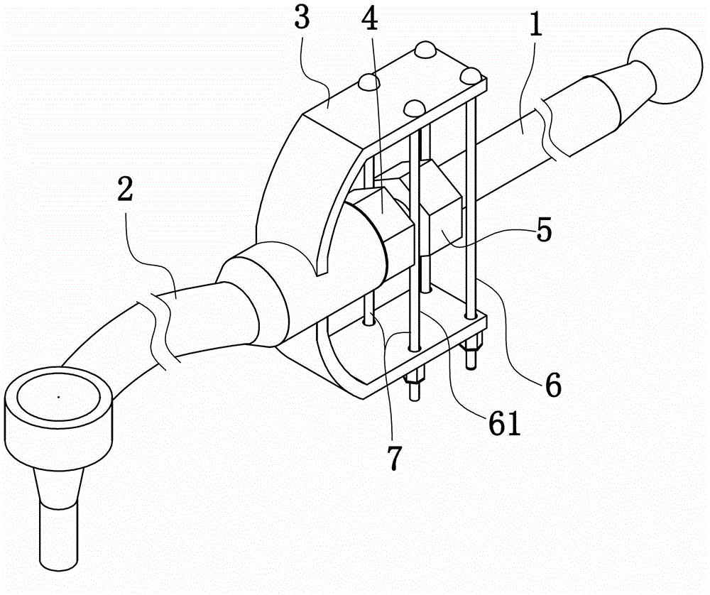
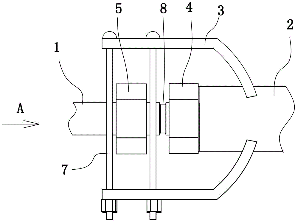
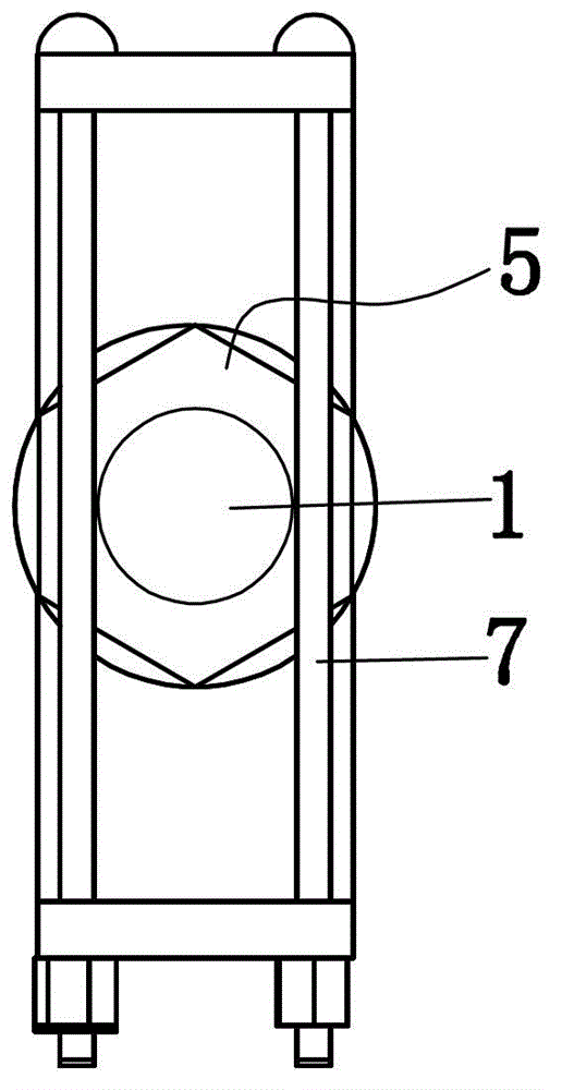
[0021] Embodiment 1: as figure 1 , figure 2 , image 3 As shown, a power steering tie rod is composed of an inner tie rod 1 and an outer tie rod 2 spliced ​​together. The splicing structure between the inner tie rod and the outer tie rod includes a threaded connection hole arranged on the end surface of the outer tie rod 2, an outer thread arranged at one end of the inner tie rod 1 and a pre-tightening fixing nut 4 arranged on the outer thread. The threaded connection holes of the inner tie rod 1 and the outer tie rod 2 are connected by threads. The pre-tightening fixing nut 4 is tightened so that its end is pressed against the end face of the outer tie rod 2 . The splicing structure between the inner tie rod and the outer tie rod can also be connected by welding to the inner tie rod and the outer tie rod.

[0022] An annular blocking projection 5 is provided on the inner tie rod 1 near the splicing part of the inner tie rod 1 and the outer tie rod 2 . The annular blocki...

Embodiment 2

[0025] Embodiment 2: the remaining structure of this embodiment is with reference to embodiment 1, and its difference is:

[0026]An annular blocking projection is arranged on the outer tie rod, near the splicing part of the inner tie rod and the outer tie rod. A pair of supporting arms are arranged on the inner tie rods and near the splicing part of the inner tie rods and the outer tie rods, which are relatively distributed on both sides of the tie rods and extend toward the direction of the other tie rods. The two supporting arms are distributed on opposite sides of the annular blocking projection, and the two supporting arms close to the annular blocking projection are parallel to the inner tie rod.

Embodiment 3

[0027] Embodiment 3: the remaining structure of this embodiment is with reference to embodiment 1, and its difference is:

[0028] Such as Figure 4 As shown, between the two supporting arms 3 , there are stoppers 6 and 61 respectively located at both ends of the annular blocking projection. On the two retaining frames 6,61, there are respectively a pair of retaining rods 7 located on the inside of the end face of the annular blocking projection. The end surfaces are parallel, and a through hole is provided in the middle of the baffle plate, and the inner tie rod 1 is inserted into the through hole; the pair of baffle rods on the above-mentioned baffle frame are the baffle plates on both sides of the through hole.


PUM


Abstract

The invention discloses a power steering gear tie rod, which can prolong the failure time of the power steering gear tie rod when a splicing position between an inner tie rod and an outer tie rod has a fatigue crack, and can prompt the fatigue crack to a driver through reducing the sensitivity of the steering gear. The power steering gear tie rod is formed by splicing the inner tie rod and the outer tie rod, wherein one of the inner tie rod and the outer tie rod is provided with a circular blocking lug, and the other of the inner tie rod and the outer tie rod is provided with a pair of supporting arms which are distributed at the two opposite sides of the tie rod and extend towards the direction of the other tie rod; the supporting arms are distributed at the two opposite sides of the circular blocking lug, the positions at the two ends of the circular blocking lug between the two supporting arms and are respectively provided with a blocking frame, the positions positioned at the inner side of the end surface of the circular blocking lug on the two blocking frames are respectively provided with a blocking rod, the two blocking rods at the same blocking frame are distributed at two the opposite sides of the tie rod of the circular blocking lug, and a gap is formed between each blocking rod and the end surface of the circular blocking lug.

Description

technical field [0001] The invention relates to an automobile component, in particular to a tie rod of a power steering gear composed of an inner tie rod and an outer tie rod spliced ​​together. Background technique [0002] The tie rod of the power steering gear is the main part of the steering system of the car. When the car is in normal operation, the tie rod of the power steering gear is mainly under tension. The current power steering tie rods mainly have the following two structures, one of which is an integrated structure, and the other power steering tie rod is composed of inner tie rods and outer tie rods. When the power steering tie rod composed of the inner tie rod and the outer tie rod is damaged (usually the inner tie rod is damaged), the inner tie rod or the outer tie rod can be replaced separately. Tie rods can be used, especially by threading the inner tie rods and outer tie rods, the total length of the power steering tie rod can be fine-tuned; but this typ...

Claims


Application Information

Patent Timeline
Patent Type & Authority Patents(China)
IPC IPC(8): B62D7/20
Inventor 陈党文马芳武杨国斌赵福全
Owner HANGZHOU BRANCH ZHEJIANG GEELY AUTOMOBILE RES INST
Learn More