

Bolt combination installation device and application method
A technology combining installation and application methods, applied in the field of building decoration materials, can solve the problems of difficulty in distinguishing the direction of the bolt head, unfavorable construction operations, uneven force on the screw, and achieve the effects of increasing convenience, flexibility and efficiency.
- Summary
- Abstract
- Description
- Claims
- Application Information
AI Technical Summary
Problems solved by technology
Method used
Image

Examples
Embodiment 1
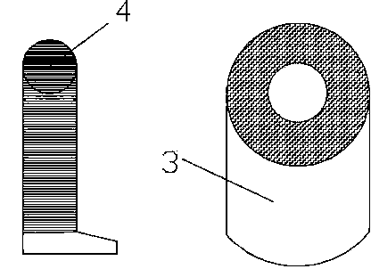
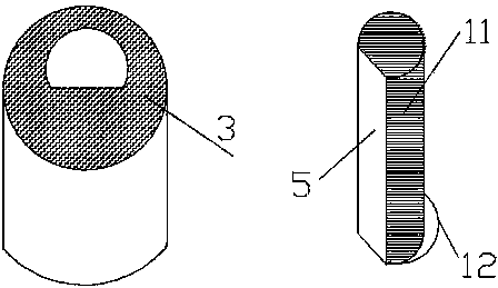
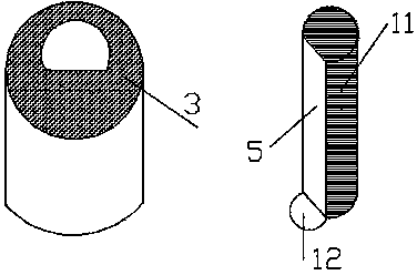
[0046] refer to figure 2 and Figure 6 , a bolt combination installation device, including a screw 1 and a nut 2, the screw 1 is composed of a rod body 11 and a countersunk head 12, the rod body 11 is a threaded rod body with a plane section 5, and the bolt combination installation device also It includes a positioning piece 3 used in conjunction with the rod body 11. The horizontal section of the positioning piece 3 is a circular cylinder, and the countersunk head 12 is all protruding from the outside of the combined body formed by the combination of the rod body 11 and the positioning piece.
[0047] The installation steps of the bolt combination installation device are as follows:
[0048] 1) On the wall 100, a slot 7 matching the shape of the combined body formed by the combination of the rod body 11 and the positioning piece 3 is provided, and a hooking slot 8 matching the countersunk head 12 is provided at the bottom of the slot 7;
[0049] 2) Insert one end of the co...
Embodiment 2
[0055] refer to figure 1 , Figure 5 and Figure 8 , a bolt combination installation device, comprising a screw 1 and a nut 2, the screw 1 is composed of a rod body 11 and a countersunk head 12, the rod body 11 is a cylindrical threaded rod body 4, and one end of the rod body 11 away from the countersunk head 12 is provided There is a groove 41, and the bolt combination installation device also includes a positioning piece 3 used in conjunction with the rod body 11. The horizontal section of the positioning piece 3 is a circular cylinder, and the countersunk head 12 is all protruded on the rod body 11 and the positioning The outside of the combined body formed by the combination of parts.
[0056] The application method of the bolt combination installation device comprises the following steps:
[0057] 1) On the veneer 200, a slot hole 7 matching the shape of the combined body formed by the combination of the rod body 11 and the positioning piece 3 is provided, and a hookin...
Embodiment 3
[0064] refer to figure 2 and Figure 7 , a bolt combination installation device, including a screw 1 and a nut 2, the screw 1 is composed of a rod body 11 and a countersunk head 12, the rod body 11 is a threaded rod body with a plane section 5, and the rod body 11 is far away from the countersunk head One end of 12 is provided with a metal strip 42. The bolt combination installation device also includes a positioning piece 3 used in conjunction with the rod body 11. The horizontal section of the positioning piece 3 is a circular cylinder, and the countersunk heads 12 are all protruded on the The outer surface of the combined body formed by combining the rod body 11 and the positioning member.
[0065] The installation steps of the bolt combination installation device are as follows:
[0066] 1) On the veneer 200, a slot hole 7 matching the shape of the combined body formed by the combination of the rod body 11 and the positioning piece 3 is provided, and a hooking slot 8 ma...
PUM
 Abstract
Description
Claims
Application Information