
Circuit for measuring transition time of ultrasonic wave by increasing voltage excitation step by step

A technology of transit time and excitation measurement, applied in measurement devices, measurement flow/mass flow, liquid/fluid solid measurement, etc., can solve the problems of complex algorithm and large error rate of ultrasonic zero-crossing point judgment, and achieve increased stability, The effect of increasing the tolerance

Inactive Publication Date: 2013-12-25
ZHEJIANG SCI-TECH UNIV
View PDF5 Cites 1 Cited by
  • Summary
  • Abstract
  • Description
  • Claims
  • Application Information

AI Technical Summary

Problems solved by technology

[0007] The purpose of the present invention is to solve the problem of high error rate and complex algorithm in the determination of ultrasonic zero-crossing point in the prior art, and to design a step-by-step voltage excitation method, which uses the signal amplitude to mark the corresponding relationship of the waveform and determine the ultrasonic wave. over time

Method used


Image

  • Circuit for measuring transition time of ultrasonic wave by increasing voltage excitation step by step
  • Circuit for measuring transition time of ultrasonic wave by increasing voltage excitation step by step
  • Circuit for measuring transition time of ultrasonic wave by increasing voltage excitation step by step

Examples


Embodiment Construction

[0021] The present invention will be further described below in conjunction with the drawings.

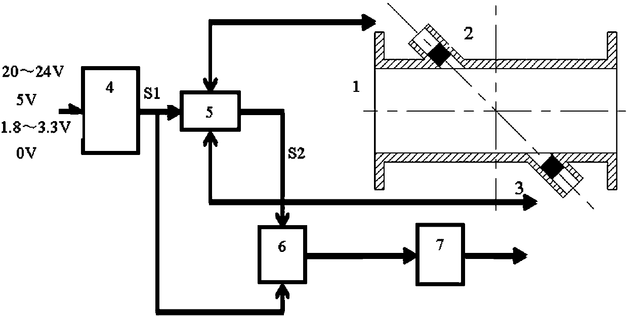
[0022] The circuit for measuring the transit time of ultrasonic wave by increasing the voltage step by step of the present invention constructs a three-level square wave sequence with the voltage amplitude gradually increasing, and at the same time, try to expand the excitation voltage difference between the levels. In the received signal, the amplitude difference will also be generated correspondingly, so that the parameter can be used as a marker of the waveform corresponding to the excitation signal to realize the measurement of the transit time. In order to realize the above logical relationship, the circuit system is equipped with: the first multi-channel strobe 4 is used to construct a square wave sequence with the voltage amplitude gradually increasing; the second multi-channel strobe 5 combines the excitation voltage and the received signal in two Two ultrasonic sensors a...


PUM


Abstract

The invention relates to a circuit for measuring the transition time of ultrasonic waves by increasing voltage excitation step by step. An ultrasonic sensor is excited by the circuit through three voltage square waves with different strength so as to realize the characteristic-point positioning for a waveform peak value and calculate the transition time of a waveform. The circuit disclosed by the invention comprises a first multipath gating (4), a second multipath gating (5) and a waveform characteristic-point judging circuit (6), wherein the first multipath gating (4) is used for selecting from four alternative voltages and constructing an excitation signal, the excitation signal is sent to a sending sensor through the second multipath gating (5), and an echo signal is led into a post-processing circuit; the waveform characteristic-point judging circuit (6) is used for judging a first zero-crossing position after each peak value according to the corresponding relation of an exciting peak value and an echo peak value to obtain a transition time difference. According to the invention, characteristic points are determined by utilizing the corresponding relation of the peak values of an exciting wave and a receiving wave, in order to avoid the condition that staggering is caused by external interference on the peak value of the receiving wave, the voltage difference of the peak values is enlarged by adopting step voltage excitation, so that the anti-interference tolerance limit is increased.

Description

Technical field [0001] The invention relates to a circuit for measuring the transit time of ultrasonic wave, in particular to a circuit for measuring the transit time of ultrasonic wave by increasing the voltage step by step. Background technique [0002] The time-difference ultrasonic flowmeter relies on detecting the modulation effect of the flowing medium on the ultrasonic signal to obtain the transit time of the sound wave on the fixed-length sound channel, so as to calculate the flow velocity data of the medium. Current ultrasonic flowmeters usually use the identification of specific mark points on the waveform to determine the transit time, so the judgment of the specific mark points on the waveform has become the key technology of the time difference ultrasonic flowmeter. [0003] In the prior art, the main methods adopted when sending out ultrasonic signals include: [0004] 1. Use a constant amplitude square wave sequence to excite and set a threshold. When the signal repli...

Claims


Application Information

Patent Timeline
Patent Type & Authority Applications(China)
IPC IPC(8): G01F1/66
Inventor 沈卫平鲍敏郑锡斌吴春华
Owner ZHEJIANG SCI-TECH UNIV
Learn More