Optical cable

An optical cable and cable core technology, applied in the field of optical fiber and cable communication and manufacturing, can solve problems such as affecting optical characteristics and transmission effects of optical fibers, unsatisfactory, damaged optical fibers, etc., to achieve the effect of small appearance and performance, easy repair, and protection of the internal structure

Active Publication Date: 2013-12-25
NANJING WASIN FUJIKURA OPTICAL COMM LTD
View PDF5 Cites 1 Cited by
  • Summary
  • Abstract
  • Description
  • Claims
  • Application Information

AI Technical Summary

Problems solved by technology

Since the special longitudinal stripping tool is very easy to damage the loose tube during stripping, and then damage the optical fiber, affecting the optical characteristics and transmission effect of the optical fiber, so this method is not ideal

Method used


Image

  • Optical cable
  • Optical cable
  • Optical cable

Examples


Embodiment 1

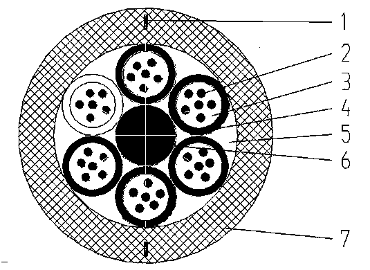
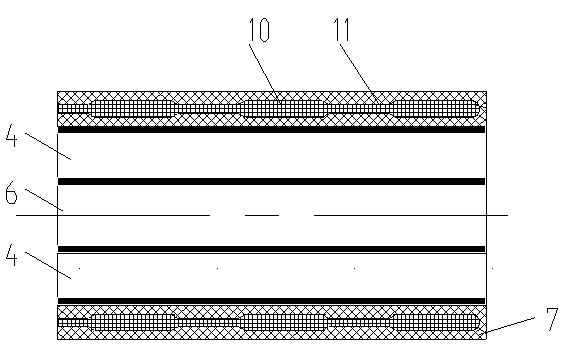
[0022] A preferred structure of the present invention is as figure 1 and figure 2 As shown, the optical cable includes a cable core and an outer sheath 7 arranged outside the cable core, the cable core includes an optical fiber 2, a loose tube 4 and a central strength member 6, the optical fiber 2 is arranged in the loose tube 4, and the loose tube 4 surrounds the The central reinforcements 6 are arranged, and two adjacent loose tubes 4 are hinged, and the outer sheath 7 is embedded with two axially extending strip-shaped separation strips. The two separation strips 1 are evenly distributed along the circumference of the outer sheath 7 .

[0023] A metal armor layer may be provided between the cable core and the outer sheath.

[0024] The thickness of the outer sheath 7 is 1.8 mm, the outer diameter of the outer sheath 7 is 13 mm, and the inner diameter is 9.4 mm.

[0025] The separation zone 1 is formed by connecting a wide unit 10 and a narrow unit 11 with a rectangular ...

Embodiment 2

[0035] In Example 2, the number of separation strips is three, which are evenly distributed in the outer sheath in the circumferential direction. The thickness of the outer sheath 7 is 1.8mm, the length of the wide unit cross-section is 1 / 2 of the thickness of the outer sheath, and the length of the narrow unit cross-section is 1 / 4 of the thickness of the outer sheath; The axial lengths of the sleeves are 1 cm and 0.8 cm respectively; the widths of the cross-sections of the wide unit and the narrow unit are both 0.1 mm. Other structures are with embodiment 1.

Embodiment 3

[0037]In Example 3, the number of separation strips is 4, which are evenly distributed in the outer sheath in the circumferential direction. The thickness of the outer sheath 7 is 1.8mm, the length of the wide unit cross-section is 2 / 3 of the thickness of the outer sheath, and the length of the narrow unit cross-section is 1 / 3 of the thickness of the outer sheath; The lengths of the units along the axial direction of the outer sheath are 1 cm and 1.5 cm respectively; the widths of the cross-sections of the wide unit and the narrow unit are both 0.15 mm. Other structures are with embodiment 1.


PUM


Abstract

The invention relates to an optical cable which comprises a cable core and an outer protection sleeve arranged outside the cable core. The cable core comprises optical fibers, loose tubes and a reinforcing piece, the optical fibers are arranged in the loose tubes which are arranged surrounding the reinforcing piece, and every two adjacent loose tubes are hinged together. The optical cable is characterized in that a plurality of band-shaped separation belts extending in the axial direction are embedded in the outer protection sleeve. In the construction process, the outer protection sleeve can be easily peeled from the optical cable through manpower, physical agility loss of optical cable constructors is lowered, and construction efficiency is improved; the skylight opening operation of the optical cable can be carried out more conveniently, and optical cable construction and maintenance risks can be lowered; the outer protection structure of the optical cable is complete, and any performance of the optical fiber is not affected.

Description

technical field [0001] The invention belongs to the field of optical fiber cable communication and manufacture, in particular to an optical cable. Background technique [0002] The basic structure of an optical cable includes a cable core and an outer sheath arranged outside the cable core. The cable core includes an optical fiber, a loose tube and a central strength member. The optical fiber is arranged in a loose tube, and the loose tube surrounds the central strength member. Arranged, hinged between two adjacent loose tubes. With the laying and application of a large number of optical cables at home and abroad, during the construction process, the requirements for the construction efficiency of communication operation and maintenance personnel are getting higher and higher, and the stripping of the outer sheath has a great impact on the construction efficiency. In the prior art, the stripping of the outer sheath mainly includes horizontal stripping and longitudinal strip...

Claims


Application Information

Patent Timeline
Patent Type & Authority Applications(China)
IPC IPC(8): G02B6/44
Inventor 曹龙飞
Owner NANJING WASIN FUJIKURA OPTICAL COMM LTD
Why Eureka
Try Eureka