

Synchronous rectification control circuit and synchronous rectification control method
A technology of synchronous rectification and control circuit, which is applied in the direction of converting AC power input to DC power output, DC power input to DC power output, irreversible AC power input to DC power output, etc., which can solve the problem of high cost and control circuit Complicated design and other issues, to achieve the effect of low cost, high-precision control, and simple control circuit
- Summary
- Abstract
- Description
- Claims
- Application Information
AI Technical Summary
Problems solved by technology
Method used
Image



Examples
Embodiment 1
[0032] An embodiment of the present invention provides a synchronous rectification control method, wherein, for the convenience of description, the description will be made from the perspective of a synchronous rectifier.
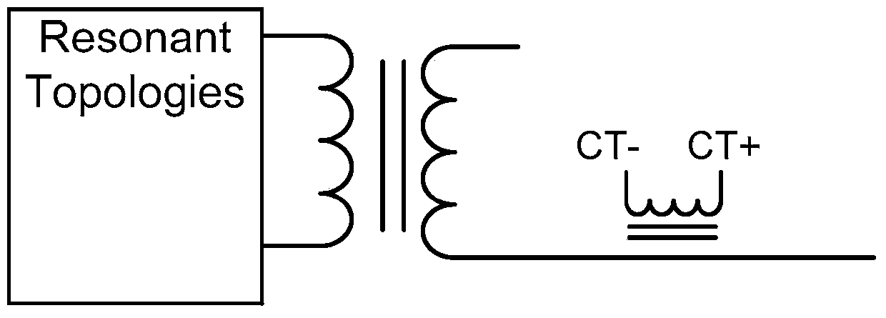
[0033] A synchronous rectification control method, comprising: connecting a current transformer CT in series to a secondary side, the CT samples the current of the secondary side to obtain a current detection signal, and outputs the current detection signal to a bridge rectifier; the bridge rectifier receives the current detection signal Signal, get the sampling current of the secondary side, and output the sampling current of the secondary side to the comparator, the comparator receives the sampling current of the secondary side, so that the comparator generates a voltage difference, prompting the output signal of the comparator to invert to control the switch of the synchronous rectifier.
[0034] see figure 1 , the specific control method flow can be as ...
Embodiment 2
[0055] In order to better implement the above solution, this embodiment also provides a synchronous rectification control circuit, which may specifically include a current transformer (CT, current transformer) 201, a bridge rectifier 202 and a comparator 203, specifically can refer to figure 2 , figure 2 It is the structural diagram of the synchronous rectification control circuit:
[0056] Among them, the current transformer 201 is used to connect the secondary side in series, sample the loop current of the secondary side, obtain the current detection signal, and output the obtained current detection signal to the bridge rectifier 202;
[0057] The bridge rectifier 202 is used to receive the current detection signal output by the current transformer 201, and obtain the secondary side sampling current according to the current detection signal, and output the secondary side sampling current to the comparator 203 so that the comparator 203 generates a voltage difference;
[...
PUM
 Abstract
Description
Claims
Application Information