System implementing a state transition having an interface storing a new next state of a self block and exchanging the state information with other block

a state transition and interface technology, applied in multiplex communication, digital transmission, instruments, etc., can solve the problems of the maximum t time delay in the timing of the alarm collection, the time required from the time when the fault is recognized by the firmware following the output of the alarm, and the problem of not being able to solv

Inactive Publication Date: 2002-08-20
HANGER SOLUTIONS LLC
View PDF3 Cites 7 Cited by
  • Summary
  • Abstract
  • Description
  • Claims
  • Application Information

AI Technical Summary

Problems solved by technology

However, there have been problems to be resolved in the related art described above.
That is, the firmware used to control the state transition of each portion of the transmission equipment reads, by polling, each alarm written in the said memory at a predetermined time interval T. However, because it is after a time T that the part polled immediately before the alarm is written is polled, there is a case where a maximum T time's delay in the timing of the alarm coll

Method used


Image

  • System implementing a state transition having an interface storing a new next state of a self block and exchanging the state information with other block
  • System implementing a state transition having an interface storing a new next state of a self block and exchanging the state information with other block
  • System implementing a state transition having an interface storing a new next state of a self block and exchanging the state information with other block

Examples


Embodiment Construction

The present invention will be now described in details hereinafter with reference to the accompanying drawings, in which embodiments of the invention are shown.

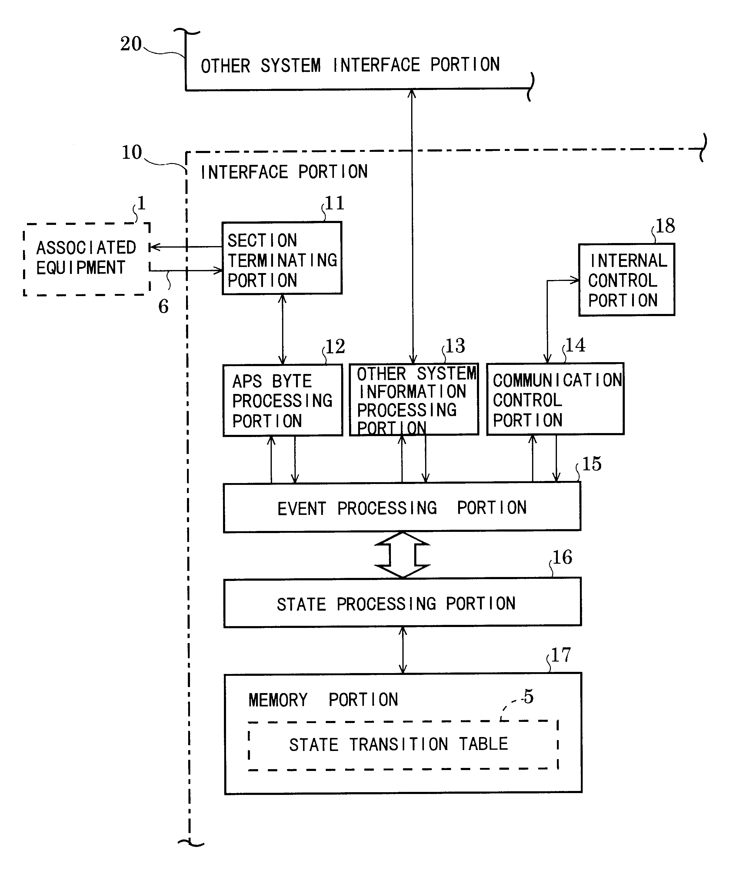
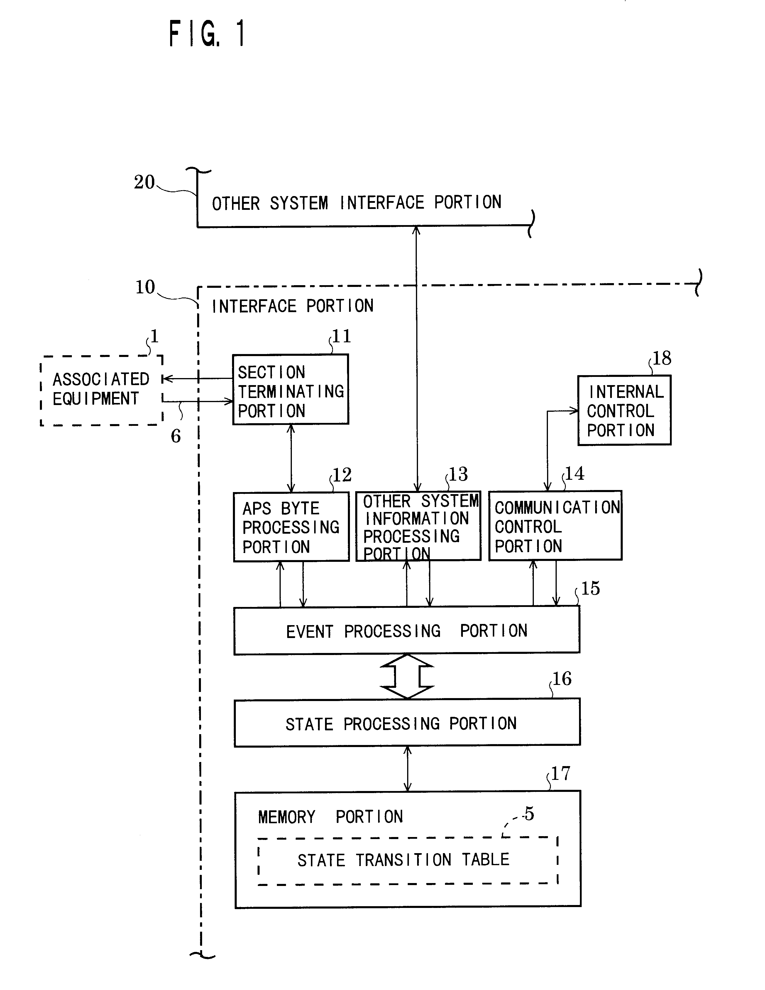
FIG. 1 is a block diagram illustrating an embodiment of a multiplexed system of the present invention. The transmission equipment described hereinafter can be divided into arbitrary numbers of the block. According to the present invention, an interface portion 10 as shown in the drawing is newly and additionally provided to all blocks within the transmission equipment so that an state transition of the system can be controlled with each block being linked with each other. The interface portion 10 is provided to a standby-system block. Other system interface portion 20 is provided to an active-system block. Thus, these blocks as well as the interface portion are duplexed. Because the structure of the other system interface portion 20 is the same as that of the interface portion 10, only the structure of the interface portion 1...


PUM


Abstract

Each block is multiplexed. Each block is provided with an interface portion (10). A section terminating portion (11) receives overhead information from an associated equipment, and an APS byte processing portion (12) converts APS bytes contained in overhead information to event information. A state processing portion (16) inputs event information and state of a self block at an address on a state transition table (5) and read out a new next state information of said self block. The transition of a state of said self block is effected to a new state and its result information is transmitted to said associated equipment and the like. Sending and receiving of state information and state transition are hard-ware controlled, causing no load to firmware and allowing a high speed switching accordingly.

Description

BACKGROUND OF THE INEVENTIONThe present invention relates to a multiplexed system which can be switched, as a whole, from a standby system to an active system and vice versa in such a system as transmission equipment wherein its each portion is multiplexed and a high degree of reliability is required.If a fault occurs in a transmission path of an active system in a SDH (Synchronous Digital Hierarchy) transmission equipment having a duplexed transmission path, the equipment detects the fault automatically, thereby allowing a system to switch from an active transmission path to a standby transmission path. Control procedures for such switching are stipulated in recommendations of ITU-T (G.707,783) which has standardized operating procedures for the transmission equipment.When a fault occurs, the transmission path or each of the transmission equipment and peripheral devices of the transmission equipment are adapted to send and receive signals for control of the switching among them, by...

Claims


Application Information

Patent Timeline
IPC IPC(8): H04L1/22H04J3/00H04J3/14
CPCH04L1/22
Inventor KAWAUCHI, HAJIME
Owner HANGER SOLUTIONS LLC
Why Eureka
Try Eureka