
Chain-transmission weeding scarifier

A technology of weeding and loosening machine and chain transmission, which is applied in the fields of land preparation machinery, agricultural machinery and implements, etc., and can solve problems such as high labor intensity, large investment of personnel, difficulty in weeding and loosening soil, etc.

Inactive Publication Date: 2014-01-01
TONGHAI DASEN IND & TRADE
View PDF8 Cites 4 Cited by
  • Summary
  • Abstract
  • Description
  • Claims
  • Application Information

AI Technical Summary

Problems solved by technology

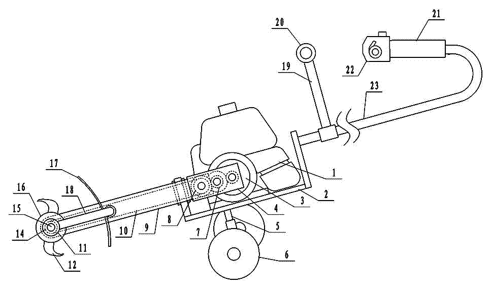
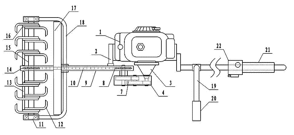
[0003] In the prior art, it is difficult to weed and loosen the soil in special mountain orchards such as coffee plantations, and the existing small-scale rotary tillers cannot work in it. The artificial weeding method requires many personnel, high labor intensity, and low work efficiency. For the problem of poor economic benefits, the present invention provides a chain drive weeding and scarifying machine. A power device is installed horizontally in the middle of the frame, and a centrifugal clutch is installed at one end of the output shaft of the power device. The transmission gear is installed in the box, the rear sprocket is installed on the output shaft of the gearbox, and a fixed frame with a cavity is installed at the front end of the frame. The rear sprocket is set in the cavity at the rear end of the fixed frame, and the front fork is installed at the front end of the fixed frame. Bearings are fixedly installed on the two ends of the front fork, and a rotating shaft is installed between the bearings. The front sprocket is installed in the middle of the rotating shaft. , there are multiple cutter heads, which are fixedly installed on the rotating shafts on both sides of the front sprocket, curved weeding knives and weed cutting knives are installed on the cutter head, and a push handle is installed on the rear end of the frame, and the handle of the push handle The controller of the power unit is installed, and the adjustment rod is installed under the frame, and the wheels are installed on the adjustment rod

Method used


Image

  • Chain-transmission weeding scarifier
  • Chain-transmission weeding scarifier

Examples


Embodiment

[0009] Example: such as figure 1 and figure 2 As shown, a chain drive weeding and scarifying machine, a power device 1 is installed horizontally in the middle of the frame 2, and a centrifugal clutch 3 is installed at one end of the output shaft of the power device 1, and the output shaft of the centrifugal clutch 3 is connected with the input shaft of the gearbox 4, and the speed is changed. The speed change gear 7 is installed in the box 4, the rear sprocket 8 is installed on the output shaft of the gearbox 4, the fixed frame 9 with a cavity is installed at the front end of the frame 2, and the rear sprocket 8 is sleeved in the cavity at the rear end of the fixed frame 9 , the front fork 18 is installed at the front end of the fixed frame 9, bearings 11 are fixedly installed on the two ends of the front fork 18, a rotating shaft 15 is installed between the bearings 11, a front sprocket 14 is installed in the middle of the rotating shaft 15, and the front end of the fixed fr...


PUM


Abstract

Disclosed is a chain-transmission weeding scarifier. A rear chain wheel is installed on a clutch which is installed at one end of a power device, a fixing frame with a cavity is mounted at the front end of a rack, the rear chain wheel is sleeved in the cavity of the rear end of the fixing frame, a front fork is arranged at the front end of the fixing frame, a rotary shaft is mounted in bearings at two ends of the front fork, a front chain wheel is mounted in the middle of the rotary shaft, the front end of the fixing frame is sleeved on the front chain wheel, and a chain is sleeved on the front chain wheel and the rear chain wheel. A plurality of cutter discs are fixed on the rotary shaft on two sides of the front chain wheel, and bent weeding cutters and winding grass cut-off cutters are mounted on the cutter discs. A push handle is mounted at the rear end of a rack and a controller of the power device is mounted on a handle shank of the push handle. An adjusting bar is installed below the rack, and wheels are mounted on the adjusting bar. During usage, an operator holds the handle shank and a handle by hands, weeding cutters below the rack are attached to the ground and can be pushed into lower portions of low fruit tree branches for weeding and soil scarifying conveniently. The chain-transmission weeding scarifier is ingenious in structure, low in weight, small in size and wide in applicable range.

Description

technical field [0001] The invention belongs to the technical field of agricultural machinery and relates to a chain drive weeding and loosening machine, which is especially suitable for weeding and loosening of mountain coffee plantations. Background technique [0002] In the prior art, what is close to the technology of the present invention is a small rotary tiller driven by the tractor head and composed of a rotary tiller, a walking mechanism and a direction control mechanism. Its volume, weight and output power are relatively large, and it is suitable for Plow and weed the open fields after the crops have been harvested. For some special orchards, such as: coffee plantations, mountain orchards, etc., the terrain is undulating, the branches of the fruit trees are low, and the branches will bear fruit. The existing small rotary tillers cannot perform weeding and loosening in these special orchards. For soil work, there are problems such as difficulty in driving in and tu...

Claims


Application Information

Patent Timeline
IPC IPC(8): A01B39/18A01B39/08
Inventor 张涛
Owner TONGHAI DASEN IND & TRADE
Learn More