
Forming equipment of spiral pipe with special section and forming method

A technology of special-shaped section and forming equipment, applied in the field of machining, can solve the problems of poor section accuracy, uneven pitch, poor section forming, etc., achieves low investment, solves uneven pitch and poor section forming, and has strong practical value. Effect

Active Publication Date: 2014-01-01
山东高原油气装备有限公司
View PDF9 Cites 16 Cited by
  • Summary
  • Abstract
  • Description
  • Claims
  • Application Information

AI Technical Summary

Problems solved by technology

[0004] In view of the defects existing in the prior art, the purpose of the present invention is to provide a forming equipment and forming method for a special-shaped cross-section spiral pipe to solve the problems of uneven pitch, poor cross-section forming and low cross-section accuracy in the existing spiral pipe processing technology. Bad question

Method used


Image

  • Forming equipment of spiral pipe with special section and forming method
  • Forming equipment of spiral pipe with special section and forming method
  • Forming equipment of spiral pipe with special section and forming method

Examples


Embodiment Construction

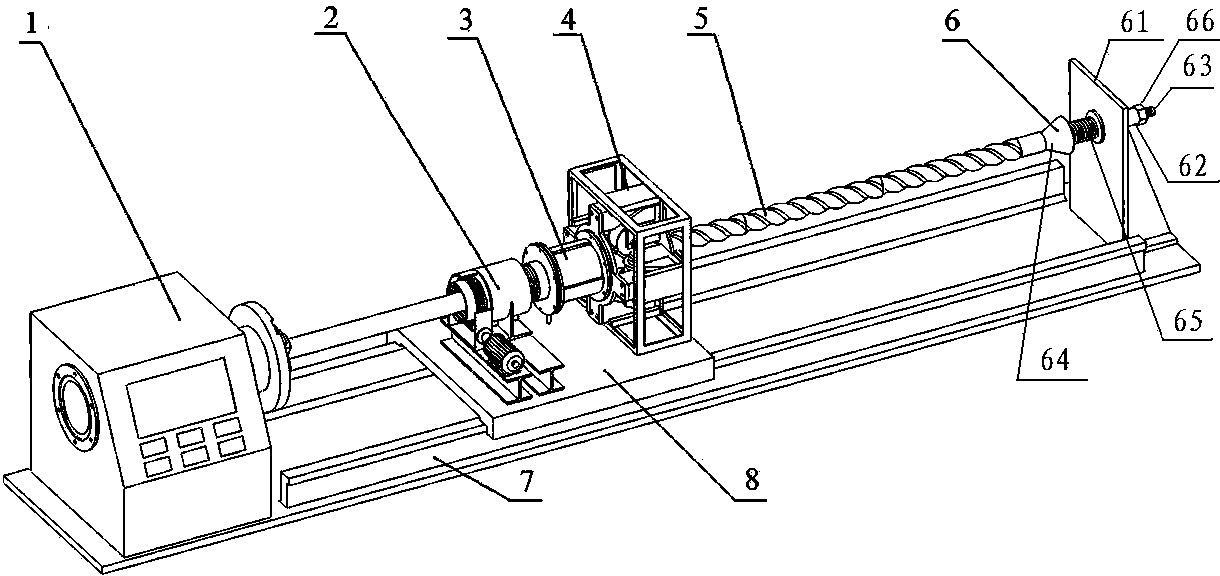
[0026] like figure 1 As shown, a special-shaped section spiral tube forming equipment, one end of the equipment is equipped with a spindle box 1 containing a chuck, and the other end is equipped with a pipe end clamping seat 6. The sliding plate 8 is installed on the sliding rail 7, and the spindle box 1 drives the sliding plate 8 to move back and forth at a given speed through a lead screw or other transmission mechanism. The sliding plate 8 is provided with an axial pushing mechanism 2 , a tube heater 3 and a radial pressing mechanism 4 . One end of the workpiece 5 (round pipe) is fixed with the chuck of the spindle box 1 , and the other end is fixed with the pipe end jacking seat 6 .

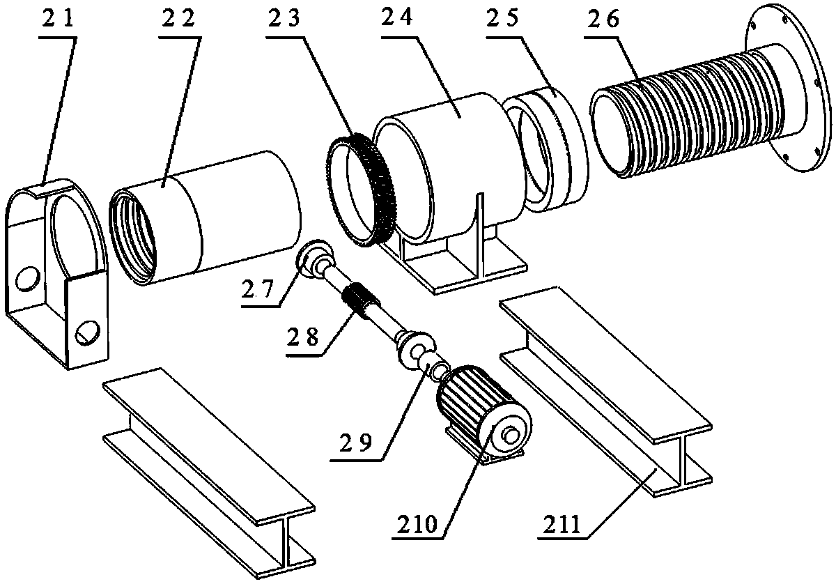
[0027] like figure 2 As shown, the axial propulsion mechanism 2 in the molding equipment adopts a screw transmission mechanism to convert the rotary motion into linear reciprocating motion.

[0028] The drive motor 210 as a power source is mounted on the base 211 and is connected with the...


PUM


Abstract

The invention discloses forming equipment of a spiral pipe with a special section and a forming method. The forming equipment comprises a rack, a main shaft box, a pipe-end jacking seat and a sliding rail, wherein the two ends of the rack are respectively provided with the main shaft box and the pipe-end jacking seat and the middle part of the rack is provided with the sliding rail; the main shaft box is provided with a chuck; the sliding rail is provided with a sliding plate which can move along the sliding rail in a reciprocating manner; the sliding plate is provided with an axial propelling mechanism, a pipe body heater and a radial pressing mechanism; the radial pressing mechanism is provided with forming rollers; when the axial propelling mechanism propels, the generated axial acting force acting on the radial pressing mechanism can be transformed into radial force for gathering the forming rollers; the main shaft box, the axial propelling mechanism, the radical pressing mechanism and the pipe-end jacking seat are arranged in sequence, and the main shaft box, the centers of the forming rollers and the pipe-end jacking seat are positioned at the same axis. The equipment and the method provided by the invention has the advantages that the spiral pipes with different section shapes can be produced, and the problem of non-uniform pitch, poor section forming and poor section accuracy and the like in cold rolling and hot rolling of the spiral pipes are solved; the forming equipment can be completely modified on the existing machine tool, is less in investment and has stronger practical value.

Description

technical field [0001] The invention relates to the field of machining, in particular to a molding device and a molding method for a helical tube with a special-shaped section. Background technique [0002] The forming technology of the spiral tube has always been a technical problem. Patent CN2858096 discloses a kind of equipment and technology for forming spiral tubes by rolling. The formed material is limited to thin-walled stainless steel tubes. Due to the lack of synchronous propulsion technology of supporting wheels, each wheel cannot be synchronously extruded under high pressure, which is not suitable for thick Precise forming of wall helical tubes with limited scope of application. [0003] In addition, the patent CN100535443 discloses an all-metal screw pump stator using an external high pressure molding method. Since the molding pressure reaches 400MPa, domestic high-pressure pumps and sealing equipment are difficult to withstand such high pressure, and the mold...

Claims


Application Information

Patent Timeline
Patent Type & Authority Applications(China)
IPC IPC(8): B21C37/12B21C37/15
Inventor 朱新忠林传宏谭帅
Owner 山东高原油气装备有限公司
Learn More