
Automatic airduct forming device

An automatic molding and blower technology, which is applied in the field of fan equipment, can solve the problems affecting the quality of the cylinder flanging, affecting the overall quality of the fan, and the decrease in roundness accuracy, so as to improve production quality, high degree of automation, and guarantee Effect of Period Accuracy

Active Publication Date:
View PDF8 Cites 0 Cited by
  • Summary
  • Abstract
  • Description
  • Claims
  • Application Information

AI Technical Summary

Problems solved by technology

[0002] Existing ventilators, especially axial flow fans, are generally composed of a fan cylinder, a motor and an impeller, and both ends of the fan cylinder are formed with outwardly extending folds, which are generally knocked manually or by semi-automatic equipment. For flanging, such as a kind of air cylinder flanging machine of Chinese patent CN2782252Y and a kind of semi-automatic air cylinder flanging machine of Chinese patent CN201841196U, it all needs to be pressed and flanged by pressing rollers, and at the same time, its cylinders all pass through the outer wall. The guide roller rotates, and there is no sleeve in the center to ensure the pressure on the inner wall of the cylinder, so that the roundness accuracy at the flanging position of the cylinder decreases when the cylinder is flanging, that is, the edge will be deformed, which greatly affects the turning of the cylinder. The quality of the edge, which affects the overall quality of the fan produced by it

Method used


Image

  • Automatic airduct forming device
  • Automatic airduct forming device
  • Automatic airduct forming device

Examples


Embodiment

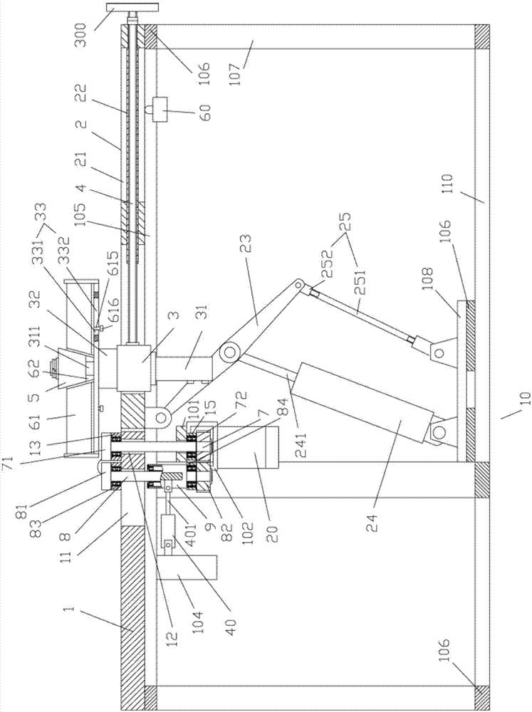
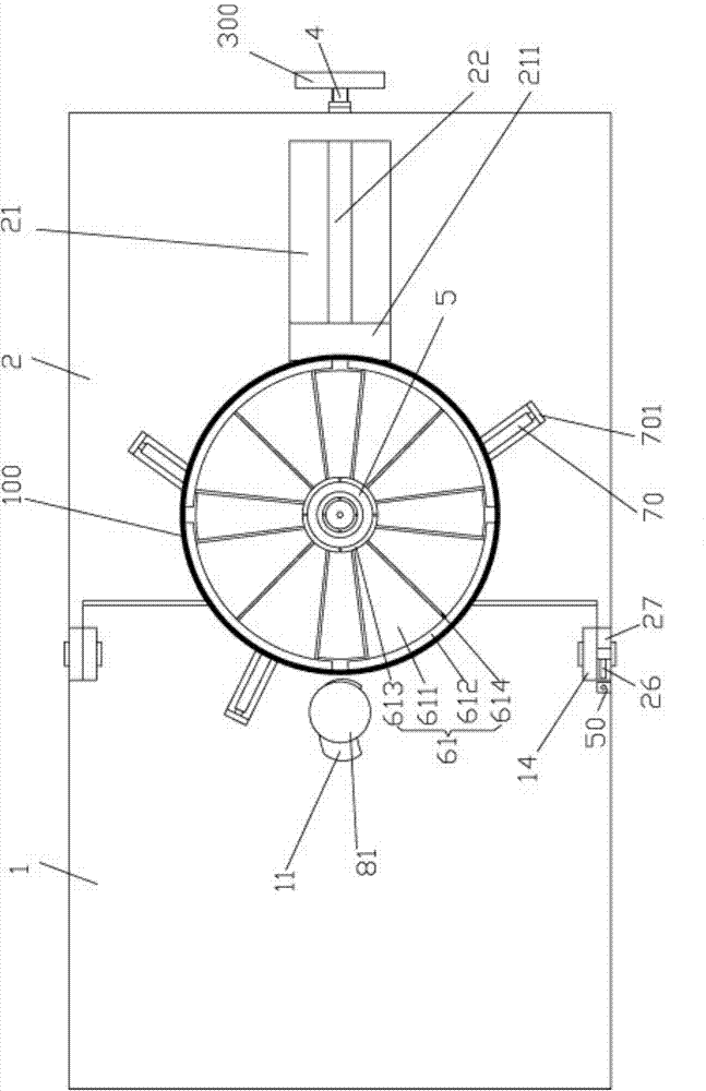
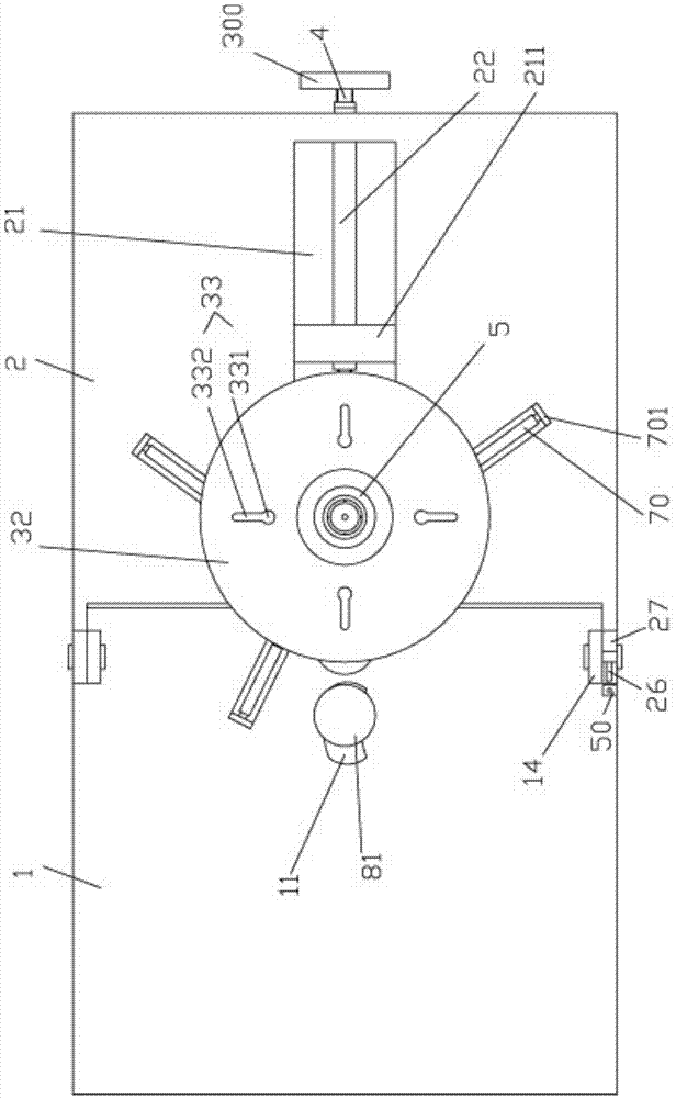
[0043] Example: see Figures 1 to 14As shown, a blower automatic forming device includes a frame 10, a support plate 1 is fixed on the top of the frame 10, and a turning plate 2 is hinged on one side of the support plate 1, and the turning plate 2 is pressed against the side of the frame 10. top;

[0044] An elongated through groove 21 is formed on the turnover plate 2, and the sliding block 3 is inserted in the elongated through groove 21. The middle part of the elongated through groove 21 is provided with an internally threaded sleeve 22, and one end of the internally threaded sleeve 22 is fixed on the long The right side wall and the other end of the elongated through groove 21 face the sliding block 3, and a through hole is formed between the right side wall of the elongated through groove 21 and the right side wall of the turnover plate 2, and the screw mandrel 4 passes through the through hole and is screwed. Connected in the internally threaded sleeve 22, the top end o...


PUM


Abstract

The invention discloses an automatic airduct forming device. A supporting plate is fixed at the top of a frame, and a turnover plate is hinged to one side of the supporting plate. A rectangular through groove is formed on the turnover plate, a slide block is sleeved in the rectangular through groove in an insertion mode, an inner thread sleeve is arranged in the middle of the rectangular through groove, a lead screw penetrates through a through hole to be screwed in the inner thread sleeve, and the top end of the lead screw is hinged onto the slide block. An oil cylinder is fixed on the bottom surface of the slide block, a push rod of the oil cylinder extends out of the slide block and penetrates through a central hole of a rotary plate fixed on the upper plane of the slide block, an inverted cone frustum is fixed at the upper portion of the rotary plate, an annular sleeve formed by at least four arcs is arranged on the rotary plate, a central through hole in a shape of an inverted cone frustum is formed in the center of the annular sleeve, and the outer wall of the cone frustum abuts against the inner wall of the central through hole. According to the automatic airduct forming device, circular degree of a cylinder during flanging is ensured by expanding the inner annular sleeve at the bottom of the inner wall of the cylinder, and production quality of the cylinder is improved. Furthermore, automatic cylinder positioning and fixation is adopted, and therefore, the automatic airduct forming device is high in automation and efficiency.

Description

Technical field: [0001] The invention relates to the technical field of ventilator equipment, in particular to an automatic spinning machine for flanging the air cylinder of the ventilator. Background technique: [0002] Existing ventilators, especially axial flow fans, are generally composed of a fan cylinder, a motor and an impeller, and both ends of the fan cylinder are formed with outwardly extending folds, which are generally knocked manually or by semi-automatic equipment. For flanging, such as a kind of air cylinder flanging machine of Chinese patent CN2782252Y and a kind of semi-automatic air cylinder flanging machine of Chinese patent CN201841196U, it all needs to be pressed and flanged by pressing rollers, and at the same time, its cylinders all pass through the outer wall. The guide roller rotates, and there is no sleeve in the center to ensure the pressure on the inner wall of the cylinder, so that the roundness accuracy at the flanging position of the cylinder d...

Claims


Application Information

Patent Timeline
Patent Type & Authority Patents(China)
IPC IPC(8): B21D19/00
Inventor 许惠中孙建江朱小强梁佳徐金标
Learn More