
Door and gate device

A technology of turnstiles and power devices, applied in the directions of roads, restricted traffic, roads, etc., can solve the problems of insufficient pressure, oil loss, large accommodation space, etc., and achieve the effect of saving cost, stabilizing the operating speed, and reducing the volume

Inactive Publication Date: 2014-01-01
ROTASUN MECHANICAL IND
View PDF4 Cites 4 Cited by
  • Summary
  • Abstract
  • Description
  • Claims
  • Application Information

AI Technical Summary

Problems solved by technology

[0002] At present, the structure of the commonly used fence machine is to actuate in the way of assisting the lifting of the fence. The design generally adopts a plumb-type gravity pressure lifting structure, that is, a weight (such as a lead weight or iron) is attached to the end of the fence adjacent to the motor. Blocks, etc.) or a stretch spring, a pull-down force is generated by the weight of the weight block or the tension of the stretch spring, and the center of gravity of the weight of the fence is shifted toward the direction of the motor by virtue of the pull-down force and the principle of moment, so that the motor works When the fence is raised by motion, the pull-down force is used to assist the fence to rise to reduce the load on the motor. However, this structure and method require a large accommodation space for setting weights or tension springs, resulting in the volume of the original fence machine. Difficult to shrink, it has the disadvantage of occupying space, and if the weight block or tension spring is placed too close to the motor, its torque is not enough to achieve the purpose of assisting in raising the fence. If the torque of the weight block or tension spring is lengthened The system takes up more space, and the auxiliary lifting effect provided by the weight block and the tension spring is limited, so the motor system still needs to choose a larger horsepower to raise the fence, making it difficult to reduce the size of the conventional fence machine, and then operate on the fence Due to the influence of gravity and the principle of leverage, the speed of the fence moving up and down is quite unstable
[0003] Another driving method of the conventional fence machine is to use an oil hydraulic cylinder to drive one end of the fence so that the fence can swing up and down with the control. can achieve the purpose of preventing unauthorized entry and exit of vehicles), so the torque is very large, resulting in a large load on the hydraulic cylinder, which is prone to oil loss, insufficient pressure to support the absence of the fence, and even damage to the hydraulic cylinder, and It is also difficult to reduce the volume of the hydraulic cylinder to provide sufficient pressure, and the finished products of the above two structures and methods can only be raised and lowered on one side

Method used


Image

  • Door and gate device
  • Door and gate device
  • Door and gate device

Examples


Embodiment Construction

[0037] In order to achieve the above-mentioned purpose and effect, the technical means and structure adopted by the present invention are hereby illustrated in detail with respect to the preferred embodiments of the present invention. Its features and functions are as follows, so that it can be fully understood.

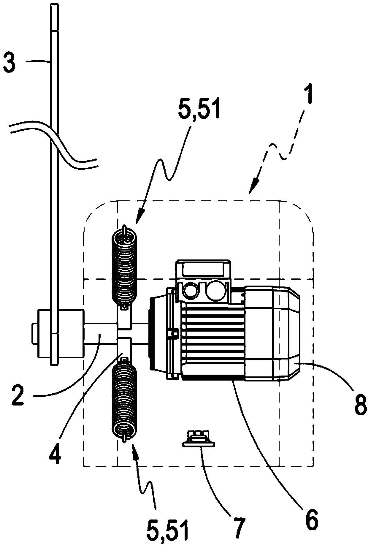
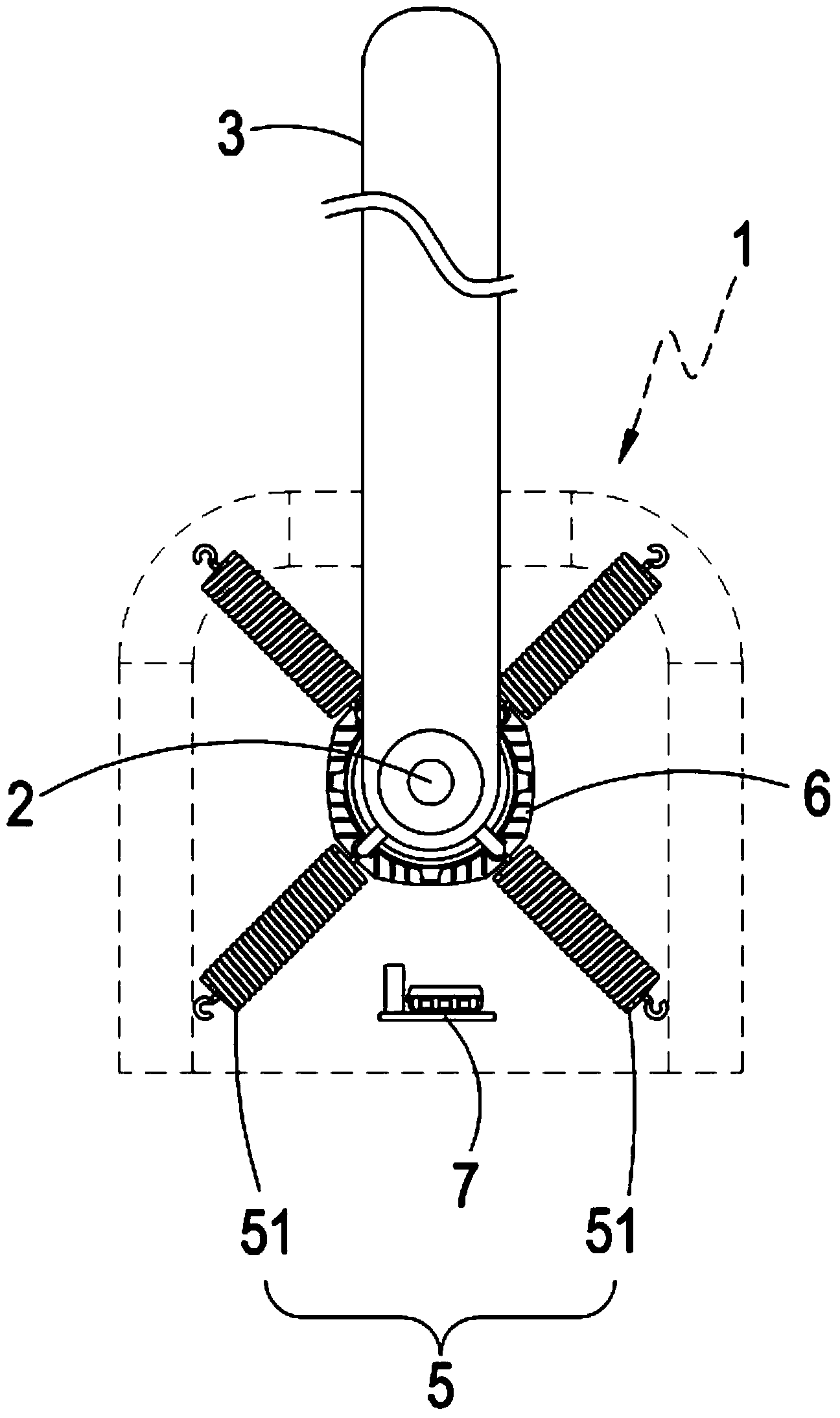
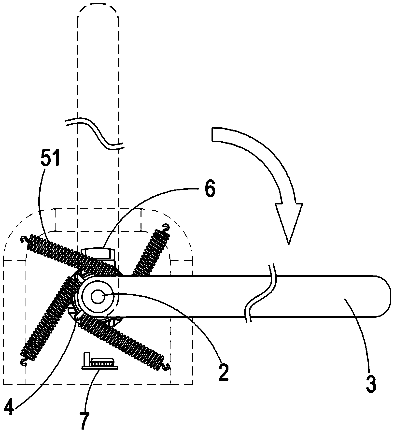
[0038] see figure 1 and figure 2 As shown, it is a schematic illustration of the implementation of the preferred embodiment of the present invention Figure 1 and implementation instructions Figure II It can be clearly seen from the figure that the present invention includes a device body 1, an axis 2, a blocking body 3, at least one connecting portion 4 and at least one elastic module 5, and the axis 2 is connected with the device body 1, And the axis 2 is further connected with at least one power device 6, and the power device 6 is a motor, and the power device 6 is further connected with at least one control device 7, and the control device 7 is further connec...


PUM


Abstract

The invention belongs to a door and gate device and belongs to the field of gate devices. The door and gate device comprises a device body, an axis connected with the device body, a stopping body connected with the axis, at least one connecting part defined on the axis and at least one elastic module; one end of the elastic module is connected with the connecting part while the other end is connected with the device body; the axis is further connected with at least one power device; when the power device is actuated, the stopping body is driven by the axis to rotate, and the connecting part is rotated by following the axis to drive the elastic module, so the elastic module is tensioned to generate an assisting force to stabilize the actuating speed of the stopping body; when the stopping body is reset, the elastic module provides an assisting force to assist the resetting. The door and gate device has the advantages of reduced size, cost saving, stable actuating speed, no direction limiting, and practical progress of actuating at left and right sides.

Description

technical field [0001] The invention provides a door and a gate device, belonging to the field of gate devices. In particular, it refers to a door and gate device with reduced size, cost saving, stable actuating speed and no direction restriction so that both left and right sides can be actuated. Background technique [0002] At present, the structure of the commonly used fence machine is to actuate in the way of assisting the lifting of the fence. The design generally adopts a plumb-type gravity pressure lifting structure, that is, a weight (such as a lead weight or iron) is attached to the end of the fence adjacent to the motor. Blocks, etc.) or a stretch spring, a pull-down force is generated by the weight of the weight block or the tension of the stretch spring, and the center of gravity of the weight of the fence is shifted toward the direction of the motor by virtue of the pull-down force and the principle of moment, so that the motor works When the fence is raised by...

Claims


Application Information

Patent Timeline
Patent Type & Authority Applications(China)
IPC IPC(8): E01F13/04
Inventor 陈信达
Owner ROTASUN MECHANICAL IND
Learn More