
Thrust bearing

a technology of thrust bearings and bearings, applied in the direction of bearings, shafts and bearings, rotary bearings, etc., can solve the problems of increasing the starting torque, increasing the lift-off/touch-down speed, and the disadvantages of past methods and apparatuses for providing hydrodynamic bearing support, etc., and achieve the effect of low torque requirements

Active Publication Date: 2009-03-03
HONEYWELL INT INC
View PDF13 Cites 11 Cited by
  • Summary
  • Abstract
  • Description
  • Claims
  • Application Information

AI Technical Summary

Benefits of technology

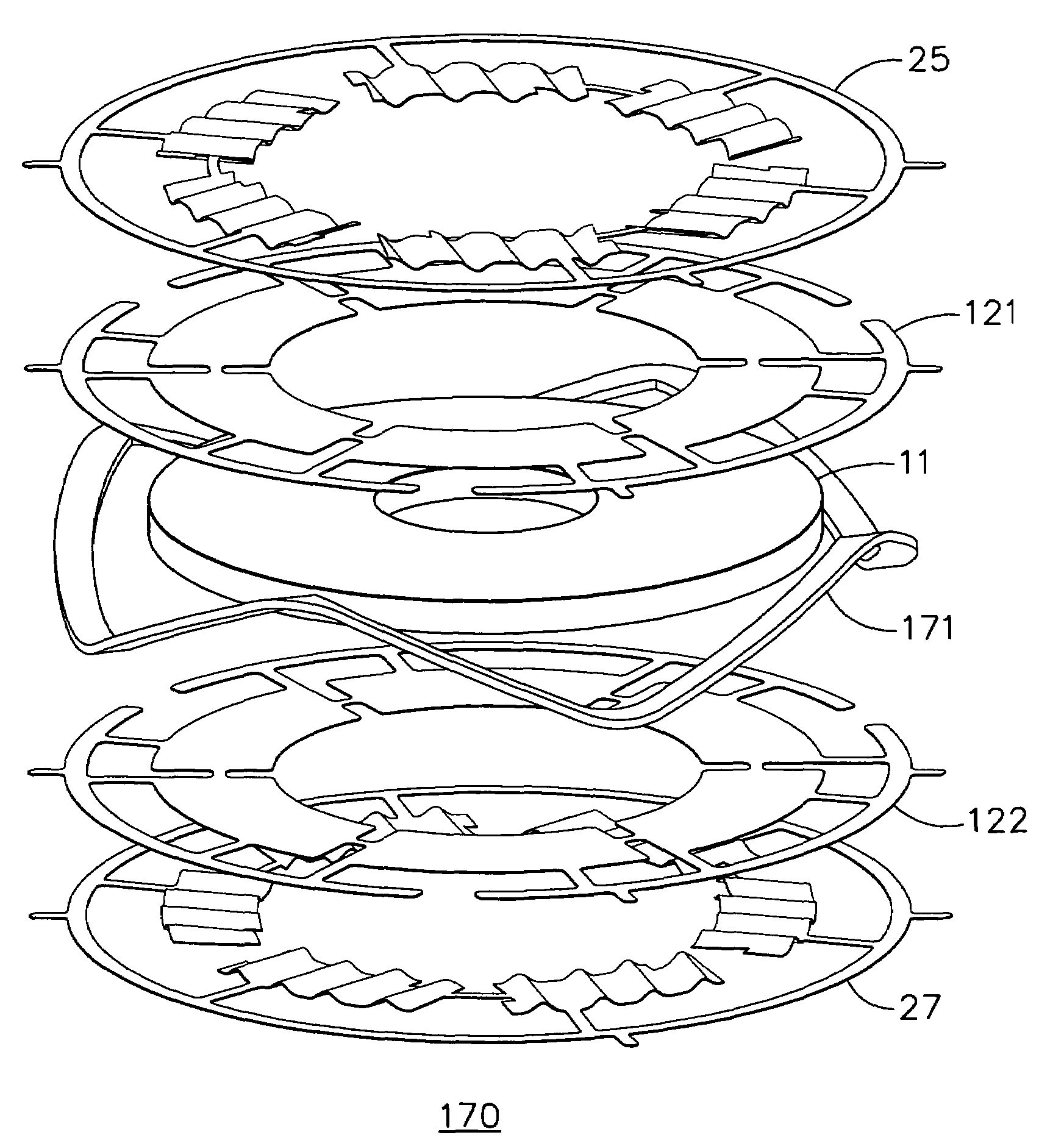
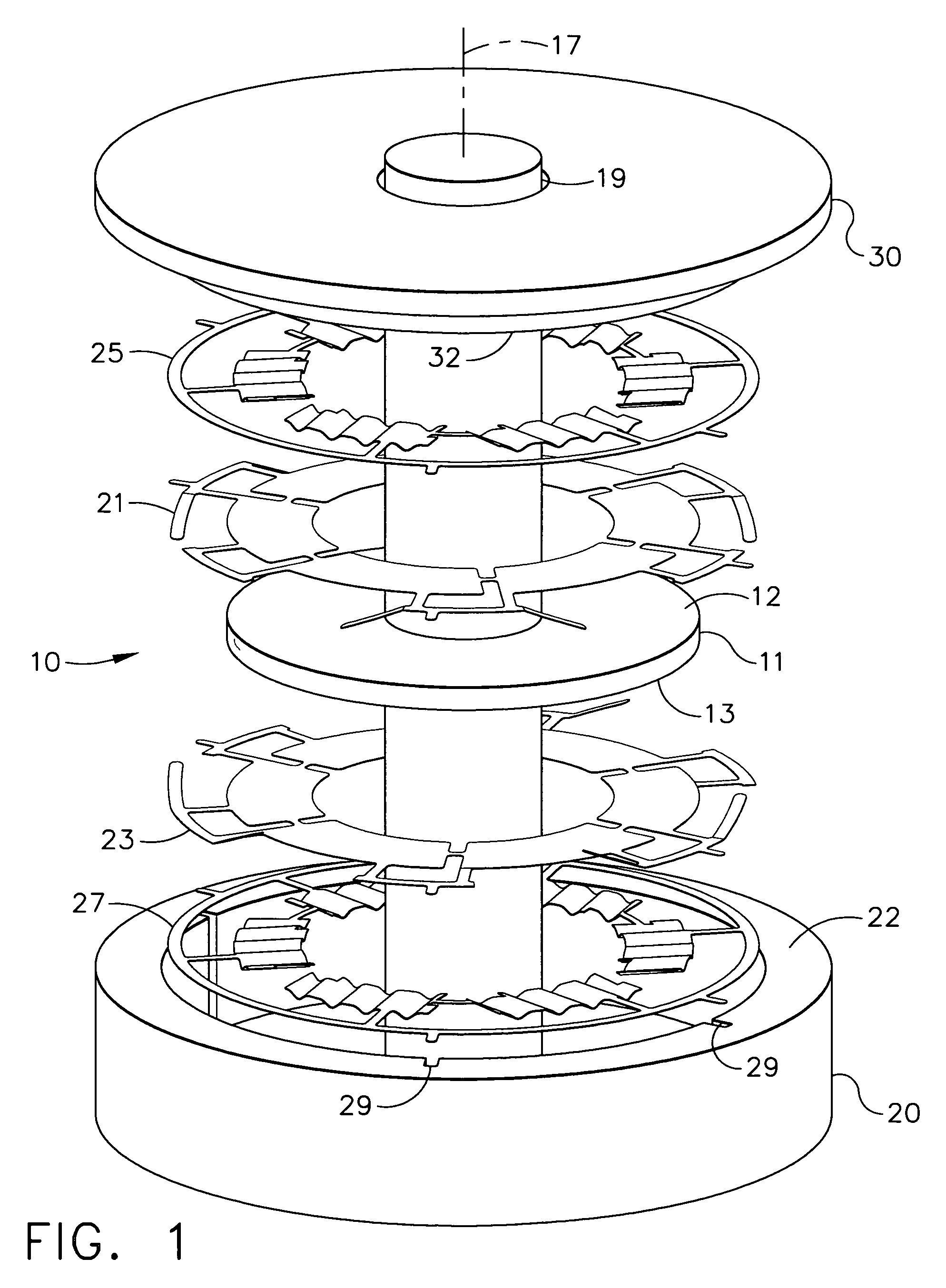
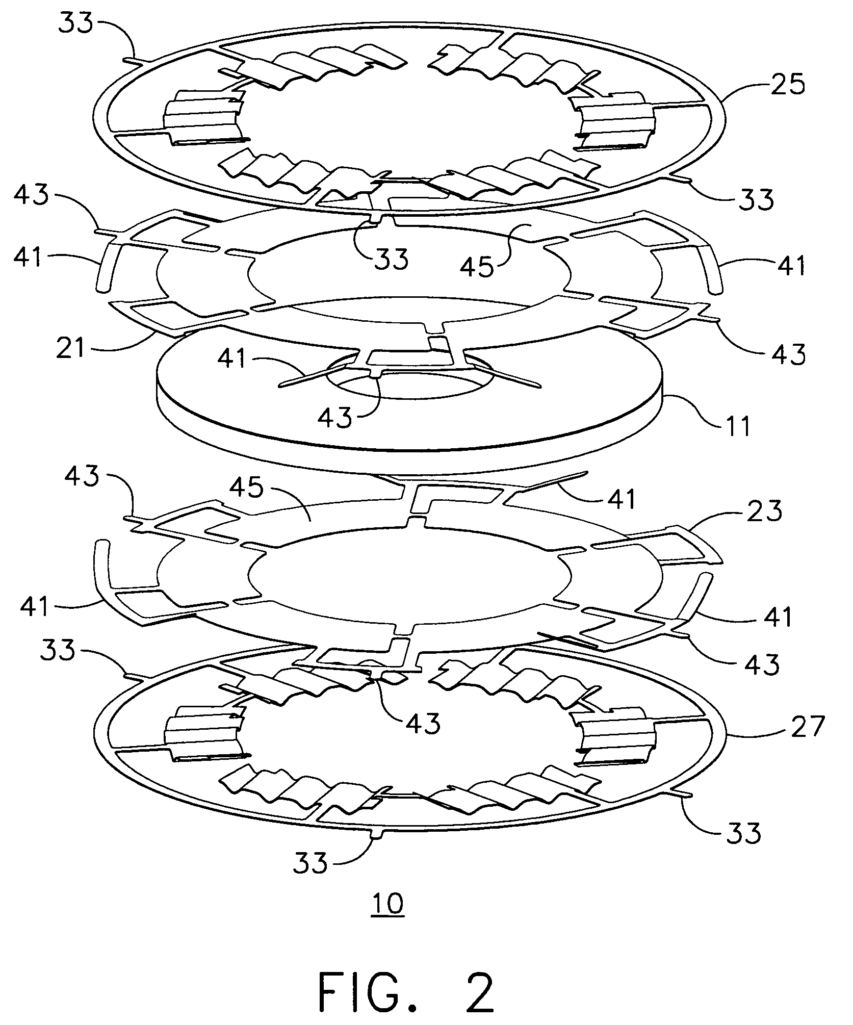
The present invention relates to a hydrodynamic bearing set for use in a housing with a thrust disk and planar surfaces. The set includes a first topfoil and a first spring, a second topfoil and a second spring, and a wavy spring. The first topfoil is secured to the housing surface and includes a plurality of dual-leaf spring pairs that contact the thrust disk and urge it away. The second topfoil is also secured to the housing surface and includes a plurality of dual-leaf spring pairs that contact the thrust disk. The set also includes a first annular ring topfoil and a second annular ring topfoil that are secured to the housing surfaces and in contact with the thrust disk to further reduce torque requirements during startup. The technical effects of the invention include reduced startup torque requirements, improved bearing support, and reduced wear and tear on the bearing components.

Problems solved by technology

Unfortunately, the past methods and apparatus for providing hydrodynamic bearing support have disadvantages.
However, this pre-load force undesirably serves to increase the starting torque of the bearing, where the starting torque should ideally be kept at a low value.
Consequently, such use of a pre-load force results in an increased lift-off / touch-down speed and may increase measurable bearing wear each time the rotating component is started or stopped.

Method used


Image

  • Thrust bearing
  • Thrust bearing
  • Thrust bearing

Examples


Embodiment Construction

[0033]The following detailed description is of the best currently contemplated modes of carrying out the invention. The description is not to be taken in a limiting sense, but is made merely for the purpose of illustrating the general principles of the invention, since the scope of the invention is best defined by the appended claims.

[0034]The present invention generally provides a hydrodynamic bearing enclosing a thrust disk and, more specifically, an improved compliant foil thrust bearing including undersprings and topfoils with peripheral dual-leaf spring pairs. The novel hydrodynamic bearing may be used in a variety of powered rotary equipment including, but not limited to, motor-driven compressors, turbochargers, turbogenerators, air cycle machinery, auxiliary power units, and propulsion engines. The dual-leaf spring pairs thereby provide a preload, positioning the hydrodynamic bearing components against a bearing housing thereby reducing the contact between the hydrodynamic be...


PUM


Abstract

A hydrodynamic bearing set, for use with a thrust disk disposed between planar surfaces of a housing, includes first and second topfoils disposed adjacent first and second thrust disk axial bearing surfaces and removably secured to the housing. An underspring is secured between each planar housing surface and the corresponding topfoil. Dual-leaf spring pairs attached to at least one topfoil periphery function to urge the topfoils away from the thrust disk axial bearing surfaces by applying a force against a planar housing surface, another topfoil, or a spacer washer secured between adjacent topfoil dual-leaf pairs or frictionally retained within the housing. Alternatively, a wavy washer, a conical spring, a Belleville washer, or a coil spring can be substituted for the dual-leaf spring pairs.

Description

BACKGROUND OF THE INVENTION[0001]The present invention generally relates to the field of hydrodynamic bearings and, more specifically, to an improved compliant foil thrust bearing set providing for a reduced startup torque requirement.[0002]Hydrodynamic bearings are utilized in many types of powered mechanical systems. These bearings are generally placed between two relatively-movable structural components, conventionally referred to as a rotating thrust runner and a stationary housing, where a working fluid is used to prevent dynamic contact between the structural components. The working fluid found in hydrodynamic bearings can be either a liquid such as oil, water, or refrigerants, or a gas such as nitrogen, oxygen, methane, hydrogen, refrigerants, or air. As low viscosity working fluids can be provided for bearing lubrication, hydrodynamic bearings are particularly suitable for applications in which the runner moves relative at a high rate of rotation relative to the housing.[000...

Claims


Application Information

Patent Timeline
Patent Type & Authority Patents(United States)
IPC IPC(8): F16C27/02F16C17/12
CPCF16C17/042F16C2360/24
Inventor SAVILLE, MARSHALLHURLEY, KEITH A.MAH, AILEENKANG, SUN GOO ALAN
Owner HONEYWELL INT INC
Learn More