
Special steel formwork for combined stairway of high-rise building and assembly method of special steel formwork

A high-rise building and combined technology, which is applied in the processing of building materials, the preparation of building components on site, and construction. It can solve problems such as concrete deformation, affecting the quality of stairs, and difficulty in demoulding, so as to increase firmness and shorten construction. The effect of cycle and easy demoulding

Active Publication Date: 2014-01-01
CHINA MCC5 GROUP CORP
View PDF5 Cites 15 Cited by
  • Summary
  • Abstract
  • Description
  • Claims
  • Application Information

AI Technical Summary

Problems solved by technology

[0004] The purpose of the present invention is to overcome the problem that the demoulding of the existing stair formwork is quite difficult, easily cause concrete deformation, and affect the quality of the stairs, and design a steel formwork and its assembly method specially used for combined stairs of high-rise buildings. The steel formwork And its assembly method By adopting the assembly structure, the deformation of the concrete can be avoided after forming, and the quality of the stairs can be guaranteed

Method used


Image

  • Special steel formwork for combined stairway of high-rise building and assembly method of special steel formwork
  • Special steel formwork for combined stairway of high-rise building and assembly method of special steel formwork
  • Special steel formwork for combined stairway of high-rise building and assembly method of special steel formwork

Examples


Embodiment 1

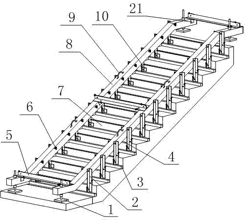
[0031] Such as figure 1 As shown, a steel formwork for combined stairs specially used in high-rise buildings includes two ladder beams 8 parallel to each other, and several horizontal rods 5 are arranged between the ladder beams 8. The ladder beams 8 are vertically connected, and the bottom surface of the horizontal bar 5 is in contact with the top surface of the ladder beams 8. On the side walls of each ladder beam 8, several stepping poles 2 are vertically arranged, and the stepping poles 2 are connected to the ladder beams 8. Fixed, the bottom of the ladder beam 8 is provided with several baffle plates 7, and the two ends of each baffle plate 7 are vertically connected with the stepping poles arranged on different ladder beams 8 respectively, and the baffle plate 7 is parallel to the horizontal bar 5. The ladder beam 8 is made of a hollow rectangular tube. The outer diameter of the rectangular tube 8 is 100mm, and the thickness is 4mm. Under the condition of meeting the str...

Embodiment 2

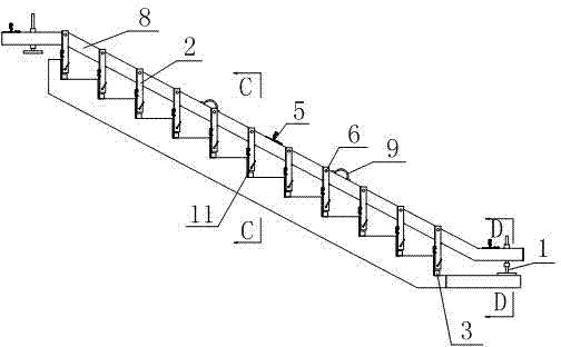
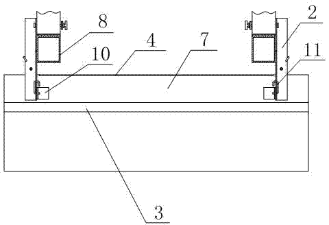
[0033] Such as figure 1 , figure 2 As shown, on the basis of Embodiment 1, the side wall and the bottom surface of the horizontal bar 5 are all provided with an angle steel adapter 21, and one end of the angle steel adapter 21 is respectively connected to the side wall of the horizontal bar 5 or The bottom surface is in contact, the other end is in contact with the ladder beam 8, and the horizontal bar 5 is provided with a buckle 11 in a U-shaped structure. Connector one 21; the outer wall of the step pole 2 is provided with an angle steel adapter two 10, and the angle steel adapter two 10 is in contact with the step pole 2 and the baffle plate at the same time, and the step pole 2 is provided with a U Buckle 11 of type structure, and buckle 11 passes step pole 2 and angle steel adapter two 10 respectively. Angle steel adapter 1 21 and angle steel adapter 2 10 are both made of angle steel, and the widths of their two sides are respectively consistent with the widths of the ...

Embodiment 3

[0035] Such as Figure 5 As shown, on the basis of the above embodiment, horizontal positioning mechanisms 6 are arranged on the opposite surfaces of the two ladder beams 8, and several waist-shaped through holes 20 are arranged on the ladder beams 8, and the horizontal positioning mechanism 6 passes through the waist Type through hole 20 is connected with stepping pole 2 behind. The waist-shaped through hole 20 refers to a through hole whose cross section is an oblong shape. By utilizing the shape of its cross section, the horizontal positioning mechanism 6 can have a space for lateral movement therein, and the lateral movement of the horizontal positioning mechanism 6 is used for stepping. The distance between the uprights 2 can be adjusted in a small range to finally ensure that the distances between the stepping uprights 2 are equal, so that after the concrete is poured, each staircase has the same shape and size.

[0036] The horizontal positioning mechanism 6 includes a...


PUM

PropertyMeasurementUnit
Outer diameteraaaaaaaaaa
Thicknessaaaaaaaaaa

Abstract

The invention discloses a special steel formwork for a combined stairway of a high-rise building and an assembly method of the special steel formwork. The special steel formwork comprises two mutually parallel stairway beams, horizontal poles are arranged between the stairway beams, two ends of each horizontal pole are perpendicularly connected with the stairway beams respectively, a stepping vertical pole is perpendicularly arranged on the side wall of each stairway beam and fixed to the stairway beam, horizontal poles are placed at two ends and the center of each stairway beam respectively, angle steel switchover pieces are attached to the side walls and the bottoms of the horizontal poles and cling to the stairway beams, U-shaped fasteners penetrate the angle steel switchover pieces and the stairway beams to serve as fixing parts, the stepping vertical poles are perpendicularly fixed outside the stairway beams, a horizontal positioning mechanism is arranged between each stepping vertical pole and the corresponding stairway beam, the bottom of each stepping vertical pole is connected with a baffle, angle steel switchover pieces are arranged on the baffles, and rib plates and fixing pipes are welded on the baffles and used for enhancing the strength of the baffles and fixing lateral timber formworks. By the aid of an assembly structure, deformation of concrete can be avoided after forming, and the quality of the stairway is ensured.

Description

technical field [0001] The invention relates to a steel formwork for stairs, in particular to a steel formwork for combined stairs specially used in high-rise buildings and an assembly method thereof, belonging to the field of construction. Background technique [0002] With the development of the modern construction industry, elevators have become common equipment in construction, but stairs are a structure that must be involved in modern buildings. Formwork, the shaft side plate adopts zigzag wooden formwork. Due to the limited physical properties of wood, it is prone to deformation during construction and under the lateral pressure of concrete. The quality of the step geometry is poor, and it is difficult to repair after the concrete is formed. The quality of concrete molding is poor, and repairing is time-consuming and labor-intensive; in addition, the production and installation of wooden formwork is time-consuming, and the loss of formwork is also relatively large. ...

Claims


Application Information

Patent Timeline
IPC IPC(8): E04G13/06E04G21/00
Inventor 叶小斌贺德福李恩亭张劲智
Owner CHINA MCC5 GROUP CORP
Learn More