Self-excited vibration principle-based microstructural fatigue test device

A fatigue test and self-excited vibration technology, which is applied in the field of basic research of micro-nano technology, can solve the problems of high cost, difficult clamping and alignment, insufficient loading load, etc., and achieve the effect of large loading load, low cost, and guaranteed accuracy

Inactive Publication Date: 2014-01-01
BEIHANG UNIV
View PDF3 Cites 4 Cited by
  • Summary
  • Abstract
  • Description
  • Claims
  • Application Information

AI Technical Summary

Problems solved by technology

[0004] The technical problem of the present invention is to overcome the deficiencies of the prior art, and provide a microstructure fatigue test device based on the principle of self-excited vibration, which

Method used


Image

  • Self-excited vibration principle-based microstructural fatigue test device
  • Self-excited vibration principle-based microstructural fatigue test device
  • Self-excited vibration principle-based microstructural fatigue test device

Examples


Embodiment Construction

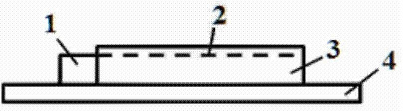
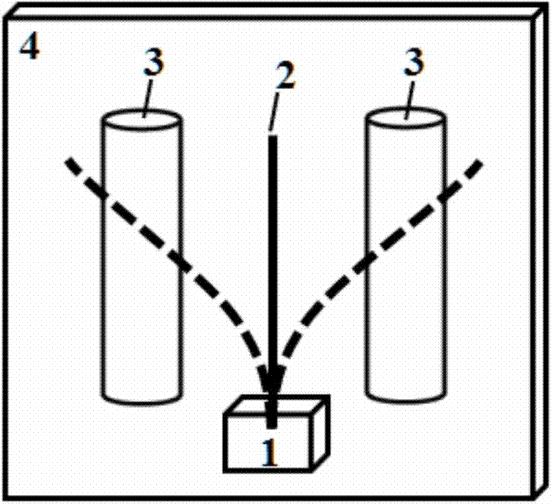
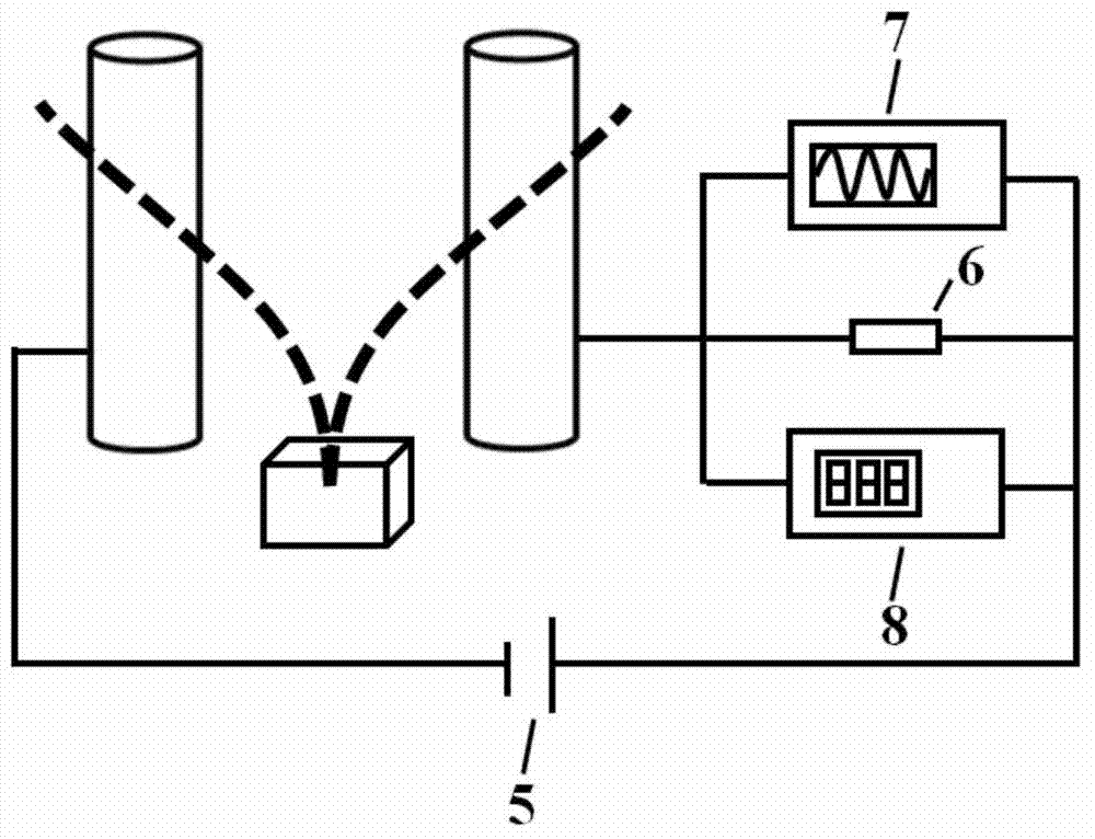
[0030] Such as figure 1 , 2 As shown, the present invention provides a microstructure fatigue test device based on the principle of self-excited vibration, including: an insulating support base 1 (a cuboid in this embodiment, length*width*height is 6mm*3mm*3.3mm), The insulating support base is not connected to any electrode, nor is it grounded, and is in a potential floating state; a conductive micro-specimen 2 (a cylinder in this embodiment, 15-20 mm long, 20-60 μm in diameter), the micro-test One end of the component 2 is fixed on the above-mentioned insulating support base 1, and the other end is suspended horizontally; two DC drive electrodes 3 (in this embodiment, a cylinder with a diameter of 3 mm and a length of 20 mm), the two electrodes 3 and The micro-test pieces are parallel and keep a certain distance (8-10mm), one of the electrodes is connected to a positive DC voltage (0~+3000V), and the other electrode is connected to a negative DC voltage (0~-3000V); The bot...


PUM

PropertyMeasurementUnit
Diameteraaaaaaaaaa
Heightaaaaaaaaaa

Abstract

The invention discloses a self-excited vibration principle-based microstructural fatigue test device which comprises an insulating supporting base, a microtest piece, two direct-current driving electrodes and a substrate, wherein the insulating supporting base is neither connected with any electrode nor grounded, and is in a potential floating state; one end of the microtest piece is fixedly arranged on the insulating supporting base, and the other end is in a horizontal suspension state; a certain clearance is kept between the two direct-current driving electrodes, and the two direct-current driving electrodes are arranged at two sides of the microtest piece and are in parallel to the microtest piece, wherein one direct-current driving electrode is connected into direct-current positive voltage, and the other direct-current driving electrode is connected into direct-current negative voltage; the insulating supporting base and the direct-current driving electrodes are fixedly arranged on the substrate. The self-excited vibration principle-based microstructural fatigue test device is simple in structure, and avoids the problems of being difficult to clamp and align; a large enough low-cycle fatigue test load can be provided without the need of prefabricating a gap on the microtest piece or placing the microtest piece in the vacuum environment; the fatigue tests of a plurality of microtest pieces can be simultaneously performed with relatively low cost, and the load cycle number can be conveniently recorded.

Description

technical field [0001] The invention relates to a microstructure fatigue test device based on the principle of self-excited vibration, which belongs to the field of basic research of micro-nano technology. Background technique [0002] MEMS devices are often subjected to harsh working conditions such as large shocks, large vibrations, and high temperature gradients. At this time, mechanical components such as micro-beams and micro-films in the device will produce excessive deformation and stress-strain, which may cause low-cycle fatigue damage. Therefore, at the beginning of the design of MEMS devices, the low-cycle fatigue of its mechanical parts should be considered, and corresponding low-cycle fatigue tests should be carried out. However, the size of microstructures is so small that traditional large fatigue test devices cannot be loaded, so it is necessary to study new fatigue test devices and methods for microstructures. [0003] Existing microstructure fatigue test de...

Claims


Application Information

Patent Timeline
IPC IPC(8): G01N3/38
Inventor 闫晓军漆明净
Owner BEIHANG UNIV
Why Eureka
Try Eureka