Annular optical filter wheel

A filter wheel and filter technology, which is applied in the field of space optical remote sensing, can solve the problems of large focal plane, bulky filter wheel, and limit the feasibility of remote sensing cameras in orbit, etc. The effect of imaging width

Active Publication Date: 2014-01-01
BEIJING RES INST OF SPATIAL MECHANICAL & ELECTRICAL TECH
View PDF3 Cites 28 Cited by
  • Summary
  • Abstract
  • Description
  • Claims
  • Application Information

AI Technical Summary

Problems solved by technology

However, the high-resolution camera has a long focal length and a large focal plane, and the filtering scheme and filter design of this type of camera optical system have encountered great challenges
If a time-sharing filter wheel is used, the filter wheel is bulky, which greatly limits the feasibility of this type of remote sensing camera on orbit

Method used


Image

  • Annular optical filter wheel
  • Annular optical filter wheel
  • Annular optical filter wheel

Examples


Embodiment Construction

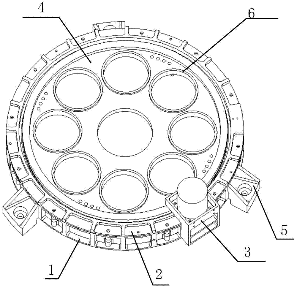
[0015] Such as figure 1 As shown, the structural composition of the present invention includes a main support structure 1 , a top flange 2 , a drive mechanism 3 , a filter disc wheel 4 , a bottom support structure 5 , and an optical filter 6 . Wherein the main support structure 1 is a ring structure, which is used as the main structure to support other components, and a bearing 17 is connected inside it. The main function of the top flange 2 is to provide axial restraint to the bearing. The driving mechanism 3 is fixed on the main supporting structure 1, and drives the filter disc wheel 4 to realize rotation. The filter 6 is fixed on the filter wheel 4 . The bottom support structure 5 is used to connect with the camera.

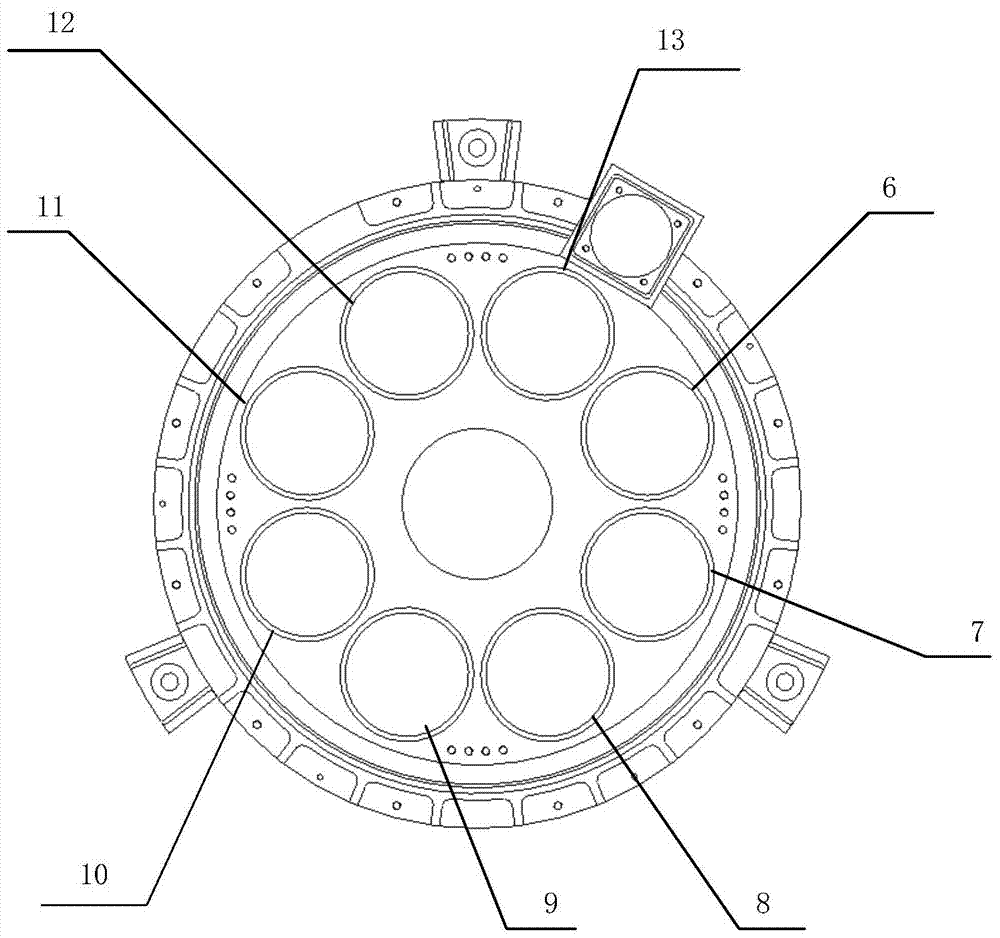
[0016] Such as figure 2 As shown, the present invention is divided into 8 channels for filtering, which are panchromatic channel 6, red channel 7, green channel 8, blue channel 9, near-infrared channel 10, 0° polarized light channel 11, and 45° polarized...


PUM


Abstract

The invention discloses an annular optical filer wheel which comprises an optical filter unit, an optical filter wheel disc unit, a main supporting structure unit, a top flange unit, a driving mechanism unit and the like. The optical filter unit divides an optical system into eight imaging detection channels, namely, a red light channel, a green light channel, a blue light channel, a near-infrared channel, a panchromatic channel, a 0-degree polarized light channel, a 45-degree polarized light channel and a 90-degree polarized light channel. The annular optical filer wheel has the advantages of being capable of achieving multi-channel filtering, detecting different areas respectively at the same time and being rotated fast. After the annular optical filter wheel rotates by one circle, multi-spectral and polarization detection of each target area is finished. The annular optical filer wheel is particularly suitable for design of the filter wheels of optical systems of large diameters, large focal lengths and annular view fields.

Description

technical field [0001] The invention belongs to the technical field of space optical remote sensing, and in particular relates to a multi-channel detection design of a circular field of view optical system of a high-resolution large-aperture optical remote sensing camera. Background technique [0002] In the design of high-resolution large-aperture remote sensing cameras, in order to meet the multi-channel detection of "panchromatic + multi-spectral + polarization + any other spectral band", a circular field of view optical system is required. The optical system can not only use the central field of view to image any other spectral band, but also use the peripheral annular field of view to perform multi-channel imaging detection of "panchromatic + multi-spectral + polarization". However, high-resolution cameras have long focal lengths and large focal planes, and the filtering scheme and filter design of this type of camera optical system have encountered great challenges. I...

Claims


Application Information

Patent Timeline
Patent Type & Authority Applications(China)
IPC IPC(8): G03B11/00G02B7/00
Inventor 苏云李岩阮宁娟王超吕红陈晓丽李锦胜
Owner BEIJING RES INST OF SPATIAL MECHANICAL & ELECTRICAL TECH
Why Eureka
Try Eureka